
Install Instructions

All Rights Reserved.
E219732---08/11
ASCO Valves
EASCO Valve, Inc.R 50 Hanover Road, Florham Park, New Jersey 07932 www.ascovalve.com
(Section2of2)
Installation & Maintenance Instructions
SERIES
OPEN--FRAME, GENERAL PURPOSE, W ATERTIGHT/EXPLOSIONPROOF SOLENOIDS
r
I&M No.V6584R11
8003G/H
8202G/H
NOTICE: See Installation and Maintenance Instructions, I&M No. V6584R12 --- Section 1 of 2 for detailed instructions.
Torque Chart
Part Name Torque Value in Inch---Pounds Torque Value in Newton---Meters
solenoid base sub ---assembly 175 ± 25 19,8± 2,8
pipe adapter 90 maximum 10,2 maximum
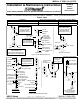
Series 8202G
without
adapter
red cap
solenoid with
1/2I NPT
core (small end up)
retainer gasket
finger washer
grounding wire---
green or green
with yellow stripes
Air Only Construction
Alternate Construction
Figure 1. Series 8003G/H Solenoids
Figure 2. Series 8202G/H Solenoids
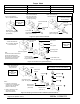
Remove red cap and
push solenoid down.
Then pry here to lift
nameplate/retainer
and push to remove.
finger washer
Side View
collar to face
valve body
Remove red cap and
push solenoid down.
Then pry here to lift
nameplate/retainer
and push to remove.
red cap
nameplate/
retainer
grounding
w i r e --- g r e e n
or green with
yellow stripes
solenoid with
1/2I NPT
0.9375--- 26UNS ---2A
thread
core
(AC)
core
(DC)
Tapped hole in core
0.250--- 28UNF ---2B
0.63 minimum full thread (AC)
0.38 minimum full thread (DC)
.062” to .093”
(1.57 to 2.36mm)
max. thickness of
panel for mounting
finger washer
solenoid base
sub ---assembly
0.69” (17.5mm)
diameter mounting
hole
Panel Mount
spacer
Remove red cap and
push solenoid down.
Then pry here to lift
nameplate/retainer
and push to remove.
solenoid base
sub ---assembly
bonnet washer
solenoid base gasket
plugnut assembly
retainer
stem
disc
disc spring
cutaway view to
show positioning
of retainer in
gasket recess
adapter
disc holder assembly
disc holder spring
pipe adapter
plugnut gasket
adapter gasket
nameplate/
retainer
Vent to Atmosphere
Series 8202G
with
adapter
Figure 3.
1.312” (33.3mm)
diameter
mounting hole
.075”[14GA]
(1.9mm) max.
thickness for
panel mounting
exhaust protec tor
none
3 --- Wa y C o n s t r u c t io n
red cap
Possible configurations
I&M No. V 6B6HF R
E21903 - 2/12
All Rights Reserved
I&M No. V 6584 R12
Page 5 of 6 (Section 2 of 2)