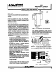
ASCOT Hi 30-60 Hanover Rd, Floral Park, Mf 07932 DESCRIPTION Hydramotor® valves consist of thees components: the actuator described in this sheet together with a mounting yoke and a valve body. H10 hydraulic actuators pull when energized and extend, powered by. an internal return spring, when energized, providing ON-OFF control of valves. The operating mechanism is completely immersed in ofl, eliminating usual maintenance and service.
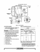
ACTUATOR ASSEMBLY NAMEPLATE tan Frye FILLER PLUG Vie" POWER Y UNIT » LMI CYLINDER SWITCH n ASSEMBLY "0 RING SE] PLATE (2 RED) b ! 4 PACKING RING TERMINAL PLATE ¢ } ASSEMBLY > NIPPLE T TRAVEL LIMIT PUSH ROD = YOKE wort] INDICATOR PLATE UNION PLATE Figure 4, H10 Cross Section STEM NUT ADJUSTMENT (See Figure 5) ACTUATOR REPLACEMENT 1. Loosen lock screw, unscrew union nit to detach valve atom from actuator shaft (see Figures 4, Detail A).
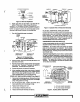
OMA SET SCREW STE BUT LEK SCREW UNION NUT Figure 5. Stem Nut Adjustment 2. Adjust upper stem nut {see Table 1) and lock with set screws. Rotate stem to align prongs with grooves, TERMINAL PLATE REMOVAL/REPLACEMENT (Figure 6) NOTE: To replace the power unit, the terminal plate must be removed to gain access to power unit mounting bolts. 1. Turn off all electrical power to actuator.
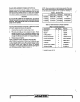
FILLING REPLACEMENT POWER UNIT WITH OIL Standard units ara filled with MIL-H-5806 oil. Units with FS in catalog number, for low ambient temperature use, are filled with Dow-Corning DC560 silicone oil. Either off is available from ASCOT General Controls and most industrial suppliers. NOTE: Stem nui and stern nut set screws are part of the naive body. When ordering parts for valve assembly, consult factory or see valve parts list (SOP H118-1 or SDP Table 2.