
User Manual


Installation instructions, BS330 base station
Technical Product Manual - DCT1800-GAP
TD 92093 (1/LZBNB 103 108 R4D) / 2005-09-23/ Ver.C
2005
64
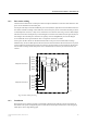
Connectors
• Two 8-pin RJ45 modular jacks for data and powering
• A 6-pin RJ12 modular jack for factory testing
The two data/powering connectors are interconnected on the board.
LEDs
LED 1 : Green power LED
LED 2 : Three colour LED, see table 1
Fig. 35 BS330 base station
Status of LED2 Meaning
Off Base station operational and no traffic on the base station
Green Base station operational and traffic on the base station
Red Base station is malfunctioning
Amber Base station is OK, but not available (self-test, not initialized, no
communication with radio exchange)
Flashing green All 8 channels are in use
Flashing amber Software is being downloaded to the base station
Table 1 Meaning of LED2
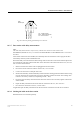
Factory
testing
(RJ12)
Data/
power
(RJ45)
Data/
power
(RJ45)
Front view Back view
LED1
LED2
037