
User Manual


Installation instructions, BS330 base station
Technical Product Manual - DCT1800-GAP
TD 92093 (1/LZBNB 103 108 R4D) / 2005-09-23/ Ver.C
2005
69
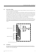
Fig. 40 Connector pinning of the data/power connector
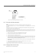
16.3.7 Base station cable delay measurement
Note:
The cable delay measurement is only necessary when the base station is connected to a CLU
REX-BRD0014 (ROFNB 157 11/2), or to an SLU board REX-BRD0015 or REX-BRD0026 with a revision lower
than R2A.
After all base stations have been installed, the cable delays must be measured in order to program the base
station delays into the system at initialization time.
Base station delays are measured at the radio exchange with an echo-meter connected to cable data pair SC0 or
SC1 and with the cable open ended at both sides. So the cable must be disconnected from the CLU, CLU-S or
SLU as well as the base station.
1. Make sure that the base station cable is unplugged from the base station.
2. Disconnect relevant connector from the relevant CLU, CLU-S or SLU.
3. Connect an echo-meter to cable pair SC0 or SC1.
4. Measure the cable delay. The measured delay is the time between sending a pulse down the line and receiving
the echo. Therefore the recorded value is twice the cable delay and must be halved. The resulting value
must have an accuracy of 200 ns (corresponding with 20 – 30 m).
5. Record on paper the delay value measured for each base station in microseconds, together with the base
station number.
6. Repeat the delay measurement for all base stations connected to the CLU, CLU-S or SLU.
7. Re-connect the connectors to the CLU, CLU-S or SLU.
If applicable repeat the delay measurement for the base stations connected to the other CLUs and SLUs.
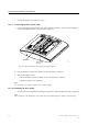
16.3.8 Sticking the label on the base station
Brand labels have to be ordered separately.
R
J45
m
odular jack
EPP-b
EPP-a
SC1-a
SC0-a
SC0-b
SC1-b
NC
NC
NC
=
Not connected
EPP
=
Express Power Pa
ir
SC = Serial Channel
0
42