TD 92417GB PRELIMINARY User Manual Ascom a71 Alarm Transceiver and Ascom p71 Transceiver 2007-02-19/ Ver.
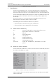
User Manual Ascom a71 Alarm Tranceiver and Ascom p71 Transceiver TD 92417GB PRELIMINARY Contents 1 Introduction............................................................................................................. 1 1.1 Abbreviations and Glossary ................................................................................ 1 1.2 Ascom a71 and p71 Versions ............................................................................. 1 2 Description...............................................
User Manual Ascom a71 Alarm Tranceiver and Ascom p71 Transceiver TD 92417GB PRELIMINARY 7 Navigate the Menu ............................................................................................... 14 7.1 Enter/Exit the Menu ......................................................................................... 14 7.2 Shortcut Keys ................................................................................................... 14 8 Menu Tree ....................................................
User Manual Ascom a71 Alarm Tranceiver and Ascom p71 Transceiver TD 92417GB PRELIMINARY 9.5.2 Location Test ............................................................................................ 23 9.5.3 Error Log .................................................................................................. 23 9.5.4 GUI Test ................................................................................................... 23 9.5.5 MD/NM Test ....................................................
User Manual Ascom a71 Alarm Tranceiver and Ascom p71 Transceiver 1 Introduction TD 92417GB PRELIMINARY This document describes the Ascom a71 Alarm Transceiver and p71 Transceiver. The Ascom a71 Alarm Transceiver and p71 Transceiver included in the On Site Paging and Personal Security System are easy to use and designed to function in tough environments.
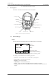
User Manual Ascom a71 Alarm Tranceiver and Ascom p71 Transceiver 2 TD 92417GB PRELIMINARY Description This section describes the transceivers and its accessories. Figure 2. Soft key field Pull-cord Soft keys OK key C key OK C Mute button Navigation key Menu key LED 002 Return key IR-receiver Alarm button Figure 2. Overview of the transceiver 2.1 General Design Display The icons and text in the display shows accessible functions and settings. Figure 3.
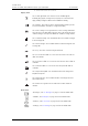
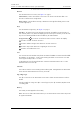
User Manual Ascom a71 Alarm Tranceiver and Ascom p71 Transceiver Display Icons TD 92417GB PRELIMINARY The “Audio signal Off” icon is shown when all alert signals, including ring signal, message tone, key beep etc. are turned off. High priority messages will however override this setting. The “Battery” icon is always shown in the display in stand-by mode. When the level is low it is time to charge the battery. The “New message” icon appears when a new message is received.
User Manual Ascom a71 Alarm Tranceiver and Ascom p71 Transceiver Buttons TD 92417GB PRELIMINARY The transceiver has two buttons, see figure 2 on page 2. Alarm button, used to send alarms. The button can also be used for test alarm. The function of this button is configurable. Mute button, used to silence the beep, vibrator and LED signals including the Acoustic Location Signal (ALS). Keys The transceiver has eight keys, see figure 2 on page 2.
User Manual Ascom a71 Alarm Tranceiver and Ascom p71 Transceiver TD 92417GB PRELIMINARY SIM Card All personal settings in the transceiver are programmed and stored in the SIM card. The SIM card can easily be moved to another transceiver. By this it is easy to keep personal settings, such as identity and alert signal. This can be handy in case of break down or when changing operation environment and switching transceiver. Pull-cord (Option) 004 Figure 4. Figure 4.
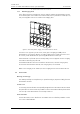
User Manual Ascom a71 Alarm Tranceiver and Ascom p71 Transceiver 2.2.3 TD 92417GB PRELIMINARY PCR Charging Rack The wall mounted PCR Charging Rack (PCR) is used for charging the transceivers. The PCR is a modular system that consists of a master module (PCR-M), extension modules (PCR-E) and power supplies. Each PCR module has six charging slots. 006 Figure 6. Figure 6.
User Manual Ascom a71 Alarm Tranceiver and Ascom p71 Transceiver 3 Safety Instructions TD 92417GB PRELIMINARY For safe and efficient operation of the transceiver, observe the guidelines given in this manual and all necessary safety precautions when using the transceiver. Follow the operating instructions and adhere to all warnings and safety precautions located on the product, the Quick Reference Guide and this User Manual.
User Manual Ascom a71 Alarm Tranceiver and Ascom p71 Transceiver 4 Basic Operation TD 92417GB PRELIMINARY Note: The transceiver may have functions other than described, depending on the preprogrammed parameters. 4.1 Switch the Transceiver On/Off To switch the transceiver On: 1 Press and hold 2 Press "Yes" soft key. OK . To switch the transceiver Off: 4.2 1 Press and hold 2 Press "Yes" soft key. Mute the Transceiver 1 4.3 . Press and hold the “Mute” button. is shown in the display.
User Manual Ascom a71 Alarm Tranceiver and Ascom p71 Transceiver 5 Alarm Functions TD 92417GB PRELIMINARY To secure a safe transmission of an alarm, every alarm is sent in two sequences. The number of times to resend an alarm in each sequence is configurable with parameters and is done in the PDM. A beep/vibrator/LED signal can confirm that an alarm has been sent. These feedback signals of a sent alarm are all configurable.
User Manual Ascom a71 Alarm Tranceiver and Ascom p71 Transceiver TD 92417GB PRELIMINARY signal always starts with a pair of low volume beeps and then continues with high volume beeps, and is alternating with the vibrator. Press any button during this warning phase to prevent the alarm from being sent. If no button is pressed an alarm is sent. Depending on set parameters, a beep/vibrator/LED signal confirms that the alarm has been sent.
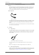
User Manual Ascom a71 Alarm Tranceiver and Ascom p71 Transceiver TD 92417GB 007 PRELIMINARY Figure 7. Figure 7. IR-function of transceiver. Configuration of Location Function The following parameters are configurable: • Reading of location code interval • Beep activation when receiving the location • LED activation when receiving the location 5.
User Manual Ascom a71 Alarm Tranceiver and Ascom p71 Transceiver 6 Messaging 6.1 TD 92417GB PRELIMINARY Messages List The twenty last received messages are stored in a message list. 6.1.1 Read a Stored Text Message Open the message list by pressing or from the menu. Navigate the list using The selected message is highlighted. Press OK to read the message. Skip between messages by using . . If the clock and date function is set, the time when the message was received can be seen.
User Manual Ascom a71 Alarm Tranceiver and Ascom p71 Transceiver 6.3 Message Queue TD 92417GB PRELIMINARY If a new message is received while another message is read the new message will replace the old message in the display. The old message will be placed in the message list and displayed when the . 6.4 Info Message An info message is shown by the icon in the display. Open the info message from the menu.
User Manual Ascom a71 Alarm Tranceiver and Ascom p71 Transceiver 7 Navigate the Menu TD 92417GB PRELIMINARY The choices in the main menu is displayed graphically with symbols, while the alternatives in the submenus are displayed as a list. 7.1 Enter/Exit the Menu 1 Enter the menu by pressing . 2 Navigate in the menu using 3 Leave any menu screen by a single press on . or press to return to idle mode. The three soft keys below the display are used for choices in the menu.
User Manual Ascom a71 Alarm Tranceiver and Ascom p71 Transceiver 8 Menu Tree 8.1 TD 92417GB PRELIMINARY Messages Figure 9. Message List Received Message 20 Info Message List Message 1 Message 2 Enter data ... Message 6 009 Send data Message 1 Message 2 Figure 9. Messages tree 8.2 Profiles Figure 10. Profile settings ... 010 Normal Silent Loud Profile 3 Profile 4 Figure 10. Profiles tree 8.3 Services Figure 11. Name: ..... Function: Soft keys: .....
User Manual Ascom a71 Alarm Tranceiver and Ascom p71 Transceiver 8.
User Manual Ascom a71 Alarm Tranceiver and Ascom p71 Transceiver 9 Menu Operations TD 92417GB PRELIMINARY A parameter setting in the SIM card determines if changes that are made from the menu is saved on the SIM card. If changes are not saved on SIM, they will be discarded when the transceiver is restarted. 9.1 Messages Here are all received messages and info messages listed. 1 Enter the menu by pressing 2 Select “Messages” and press 9.1.1 . OK .
User Manual Ascom a71 Alarm Tranceiver and Ascom p71 Transceiver 9.1.3 TD 92417GB PRELIMINARY Send Data The data send function can be used for opening a door, starting/stopping a machine etc. 9.2 1 Press . 2 Select "Messages". 3 Select “Send data”. 4 Use 5 • To insert a digit in the middle of the text string, press "Edit", use where to insert the digit. • Press "Insert" and insert the digits. • To remove a digit, press C . Enter data and press “Send”.
User Manual Ascom a71 Alarm Tranceiver and Ascom p71 Transceiver 2 TD 92417GB PRELIMINARY , a list with all created services is shown. Select “Services” and press OK Figure 15. Services Lab door Get lab results Require wheelchair Lock Close 014 Open Figure 14. Services list 9.3.1 9.4 Activate a Service 1 Select the desired service in the service list using . 2 Press OK or soft key; to activate the service. If data is sent, the text “Sending” is shown.
User Manual Ascom a71 Alarm Tranceiver and Ascom p71 Transceiver 3 9.4.2 PRELIMINARY . The transceiver will automatically Activate the choice by pressing “Save” or return to the Alert signals list. Select “Alert Signals” and press 2 Select “Increasing Volume” and press selected/cleared. OK . OK ; the Increasing Volume checkbox is Vibrator On/Off 1 Select “Alert Signals” and press 2 Select “Vibrator” and press 9.4.4 Message Reminder On/Off OK OK .
User Manual Ascom a71 Alarm Tranceiver and Ascom p71 Transceiver 3 4 Use digit. TD 92417GB PRELIMINARY to mark a digit in the virtual number pad, press OK to select the • To insert a digit in the middle of the text string, press "Edit", use where to insert the digit. • Press "Insert" and insert the digit. • To remove a digit, press C . Press "Save" and "Yes" to save the Alarm Data string. to select 9.4.
User Manual Ascom a71 Alarm Tranceiver and Ascom p71 Transceiver TD 92417GB PRELIMINARY . 1 Select “General” and press 2 Select "Group Numbers" and press 3 Select the group number using 4 Press OK OK OK . . ; the selected group number checkbox is selected/cleared. 9.4.17 Show Time and Date 1 Select “General” and press 2 Select “Show Time and Date” and Press selected/cleared. OK . OK . The Show Time and Date checkbox is 9.4.
User Manual Ascom a71 Alarm Tranceiver and Ascom p71 Transceiver 9.5.2 Location Test TD 92417GB PRELIMINARY To display the current (latest received) location: 1 9.5.3 Select "Location" and press OK . Error Log To view the error log: 1 9.5.4 Select “Error Log” and press OK , a list of recent system errors (if any) is displayed. GUI Test To test features such as LEDs, screen, backlight, vibrator, and beeps: 1 Select “GUI Test” and press 2 Select the feature to test and press 9.5.5 OK .
User Manual Ascom a71 Alarm Tranceiver and Ascom p71 Transceiver 10 Operation Notice TD 92417GB PRELIMINARY 10.1 Operation Condition Transceiver Only use the transceiver in temperatures from -10 o C to +55 oC. Avoid exposing in direct sunlight and other heat sources. Protect the transceiver from aggressive liquids and vapours. Keep the transceiver away from strong electromagnetic fields and explosive environments. Battery Do not immerse in water or throw into fire.
User Manual Ascom a71 Alarm Tranceiver and Ascom p71 Transceiver 11 TD 92417GB PRELIMINARY Maintenance Use only original accessories. Installation and repairs should be done by authorised personnel only. Keep the recharging contacts on the transceiver away from metallic and greasy objects. 11.1 Atex/EX Battery In combination with EX-versions use approved battery types only. See EC Type Examination Certificate Sira 05ATEX2310 and following supplements.
User Manual Ascom a71 Alarm Tranceiver and Ascom p71 Transceiver TD 92417GB PRELIMINARY 11.3 Change the SIM Card Note: It is recommended that the SIM card is changed in an environment without static electricity. Figure 18. 3 1 2 017 4 Figure 17. Removal and replacement of the SIM card. 1 Remove the battery, see 11.2 Replace the Battery on page 25. The SIM card is placed under the battery unit in a hatch. 2 Press down the flexible stop (1) and move the SIM card back as far as possible (2).
User Manual Ascom a71 Alarm Tranceiver and Ascom p71 Transceiver 12 Related Documents TD 92417GB PRELIMINARY Installation and Operation Manual, Portable Device Manager, Windows version TD 92325GB Quick Reference Guide, a71 Alarm Transceiver and p71 Transceiver TD 92418GB System Description, Personal Security System TD 90677GB System Description, On Site Paging System TD 91034GB Configuration Manual, Ascom a71 Alarm Transceiver and p71 Transceiver TD 92439GB Installation Manual, PCR Charging R
User Manual Ascom a71 Alarm Tranceiver and Ascom p71 Transceiver TD 92417GB PRELIMINARY Document History For details, see change bars in the document. Version Date Description A 2007-xx-xx First Released version 2007-02-19/ Ver.
User Manual Ascom a71 Alarm Tranceiver and Ascom p71 Transceiver TD 92417GB PRELIMINARY Appendix A: Programming the Transceiver The transceiver is programmed using the Portable Device Manager (PDM) software PDMSB. To program the transceiver do as below: 1 Connect the RS232 Programming Adapter to the computer. 2 The computer COM port corresponding to the RS232 Programming Adapter and the COM port settings for the PDM software must match.
User Manual Ascom a71 Alarm Tranceiver and Ascom p71 Transceiver Editing Parameters TD 92417GB PRELIMINARY When delivered, the transceiver parameters usually is pre-programmed. If any settings should be changed, the PDM can be used to edit the parameters. For instructions on how to edit parameters, see Configuration Manual, Ascom a71 Alarm Transceiver and p71 Transceiver, TD 92439GB.