
User's Manual
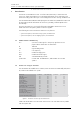
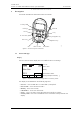
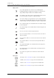
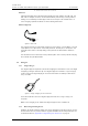
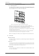
Table Of Contents
- Contents
- 1 Introduction
- 2 Description
- 3 Safety Instructions
- 4 Basic Operation
- 5 Alarm Functions
- 6 Messaging
- 7 Navigate the Menu
- 8 Menu Tree
- 9 Menu Operations
- 9.1 Messages
- 9.2 Profiles
- 9.3 Services
- 9.4 Settings
- 9.4.1 Change the Volume
- 9.4.2 Increasing Volume On/Off
- 9.4.3 Vibrator On/Off
- 9.4.4 Message Reminder On/Off
- 9.4.5 Key Beep On/Off
- 9.4.6 Deactivate/Activate Man-down alarm
- 9.4.7 Deactivate/Activate No-movement alarm
- 9.4.8 Deactivate/Activate Pull-cord alarm
- 9.4.9 Set Alarm Data
- 9.4.10 Change the Message Text Size
- 9.4.11 Backlight On/Off
- 9.4.12 Change the Contrast
- 9.4.13 Turn Automatic Key Lock On/Off
- 9.4.14 View Shortcut Keys
- 9.4.15 Select Language
- 9.4.16 Group Numbers
- 9.4.17 Show Time and Date
- 9.4.18 Set Time Format
- 9.4.19 Set Date Format
- 9.4.20 Display System Information
- 9.5 System Test
- 10 Operation Notice
- 11 Maintenance
- 12 Related Documents
- Appendix A: Programming the Transceiver

PRELIMINARY
TD 92417GB
2007-02-19/ Ver. PA
User Manual
Ascom a71 Alarm Tranceiver and Ascom p71 Transceiver
2
2 Description
This section describes the transceivers and its accessories.
Figure 2.
Mute button
Alarm button
Pull-cord
OK key
OK
C
Menu key
Return key
IR-receiver
LED
Navigation key
Soft keys
C key
Soft key field
002
Figure 2. Overview of the transceiver
2.1 General Design
Display
The icons and text in the display shows accessible functions and settings.
Figure 3.
Icon row
Date & Time
Info Doctor Jobs
Soft key field (User defined)
Call number & Status
13:2205:12:06
John Doe
In charger
Identity
003
}
}
}
}
}
4321
Figure 3. Example of a display configuration in stand-by mode.
The display can be divided into the following segments:
• Icon row - Shows information on active alarms, battery level.
• Date & Time - Shows the date and time.
• Identity - Shows the owner ID.
• Call number - Shows the call number.
• Status - Shows the status of the transceiver. For examples; In charger.
• Soft key field - Shows the user defined names of the three soft keys beneath the
display.