
User's Manual
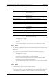
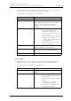

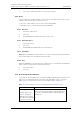
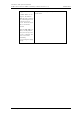

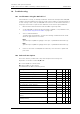
Table Of Contents
- 1 Introduction
- 2 Description
- 3 Safety Instructions
- 4 IP Security
- 5 Installation of the Base Station
- 5.1 Base Station Cabling
- 5.2 Install the Base Station
- 5.2.1 Fix the Mounting Bracket to a Wall
- 5.2.2 Fix the Mounting Bracket to a Ceiling
- 5.2.3 Fix the Mounting Bracket to a Pole or Beam
- 5.2.4 Use the Cable Ducts for IPBS1
- 5.2.5 Connect External Antennas (only IPBS2 and DB1)
- 5.2.6 Secure the Cable
- 5.2.7 Pinning
- 5.2.8 Connect the Base Station Cables
- 5.2.9 Mount the Base Station
- 5.3 Power the Base Station
- 6 Installation of the IPBL
- 7 Configuration
- 7.1 Requirements
- 7.2 Access the GUI
- 7.3 GUI Web Access
- 7.4 Configure the Mobility Master
- 7.5 Configure the Standby Mobility Master
- 7.6 Configure the Pari Master
- 7.7 Configure the Standby Pari Master
- 7.8 Configure the Master
- 7.9 Configure the Standby Master
- 7.10 Plug and Play Configuration
- 7.11 Configure the Radio
- 7.12 Configure Deployment
- 7.13 Add Users
- 8 Operation
- 8.1 General
- 8.1.1 Name the IPBS/IPBL
- 8.1.2 Change User Name and Password
- 8.1.3 Centralized Management of Administrator/Auditor Accounts Using Kerberos
- 8.1.4 Configure Automatic Firmware Update
- 8.1.5 Configure the NTP Settings
- 8.1.6 Configure Logging
- 8.1.7 Configure the HTTP settings
- 8.1.8 Configure the HTTP Client settings
- 8.1.9 SNMP
- 8.1.10 Certificates
- 8.1.11 License
- 8.2 LAN
- 8.3 IP
- 8.4 LDAP
- 8.5 DECT
- 8.5.1 Change System Name and Password
- 8.5.2 Set Subscription Method
- 8.5.3 Configure Authentication Code
- 8.5.4 Select Tones
- 8.5.5 Set Default Language
- 8.5.6 Set Frequency Band
- 8.5.7 Enable Carriers
- 8.5.8 Local R-Key Handling
- 8.5.9 No Transfer on Hangup
- 8.5.10 Configure Coder
- 8.5.11 Secure RTP
- 8.5.12 Configure Supplementary Services
- 8.5.13 Select Mode
- 8.5.14 Set Master Id
- 8.5.15 Enable PARI Function
- 8.5.16 Configure Gatekeeper
- 8.5.17 Registration for Anonymous Devices
- 8.5.18 Select Mobility Master Mode
- 8.5.19 Connect Mobilty Master to other Mobility Master(s)
- 8.5.20 Disconnect Mobilty Master from other Mobility Master(s)
- 8.5.21 Connect Master to a Mobility Master
- 8.5.22 Enable the Radio
- 8.5.23 Enter IP Address to the PARI Master and the Standby PARI Master
- 8.5.24 Multiple Radio Configuration
- 8.5.25 PARI
- 8.5.26 SARI
- 8.5.27 Configure Air Synchronization
- 8.6 VoIP
- 8.7 UNITE
- 8.8 Import and Export a Central Phonebook
- 8.9 Users
- 8.10 Device Overview
- 8.11 DECT Sync
- 8.12 Traffic
- 8.13 Gateway
- 8.14 Backup
- 8.15 Software Upgrade
- 8.15.1 Before Upgrading
- 8.15.2 Upgrading Sequence
- 8.15.3 IPBS/IPBL Upgrade
- 8.15.4 Configuration After Updating the Firmware From Software Version 2.x.x to Later
- 8.15.5 Configuration After Updating the Firmware From Software Version 3.x.x to Later
- 8.15.6 System Upgrade from Software Version 4.x.x to 5.0.x
- 8.16 System Downgrade from software version 5.0.x to 2.x.x, from 4.x.x to 2.x.x and from 3.x.x to 2.x.x
- 8.17 System Downgrade from software version 5.0.x to 3.x.x and 4.x.x to 3.x.x
- 8.18 Update
- 8.19 System Upgrade in System with Mobility Masters
- 8.20 Replacing Master Hardware in Multiple Master System
- 8.21 Diagnostics
- 8.22 Reset
- 8.23 Reset Using the Reset Button
- 8.1 General
- 9 Commissioning
- 10 Troubleshooting
- 11 Related Documents
- Document History
- Appendix A: How to Use the Update Server
- Appendix B: RFP Power Consumption
- Appendix C: Local R-Key Handling
- Appendix D: Database Maintenance
- Appendix E: Load Balancing
- Appendix F: Update Script for Configuration of Kerberos Clients
- Appendix G: Install Certificate in the Web Browser

TD 92579EN
15 February 2012 / Ver. H
Installation and Operation Manual
IP-DECT Base Station & IP-DECT Gateway (software version 5.0.x)
136
8.21.5 Performance
It is possible to check different performance parameters. For a description of the
p
arameters, see the table below.
Figure 32.
Parameter Description
CPU Shows CPU utilization
CPU-R Shows utilization of CPU resources allocated by
dif
ferent tasks
MEM Shows memory utilization
Concurrent calls Shows the number of ongoing calls
Temperature (only for IPBL) Shows the temperature of the cabinet
Voltage (only for IPBL) Shows the power supply voltage level
Current (only for IPBL) Shows the power supply current consumption
1 Select Diagnostics > Performance
2 Select the checkbox(es) for the d
esired performance statistics.
3 Click "OK".
4 One window shows statistics for the last 24 hours. The
maximum possible value is
displayed in the top-left corner. Click the left or right arrow buttons to see different
time frames.
8.21.6 Config Show
Under Diagnostics > Config Show, the configuration is displayed as a text output.
Code A unique number that identifies the alarm.
Click the
code to get more detailed information about the
alarm. For a list of possible codes and their
descriptions, see 10.2 Faul
t Code Descriptions on
page 142.
Severity It has three possible states:
• Critical - Immediate action is
r
equired. It is displayed, for
example, if a managed object goes
out of service.
• Major - Urgent action is required. It
is
displayed, for example, if the
capability of the managed object is
severely degraded.
• Indeterminate - Level of severity
can
not be determined
Remote The IP Address of the object that r
eported the alarm.
Click the IP address to access the object.
Source The software module that reported the alarm.
T
ogether with the code it uniquely identifies an
alarm.
Description A textual description of the alarm.