
User's Manual
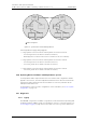


Table Of Contents
- 1 Introduction
- 2 Description
- 3 Safety Instructions
- 4 IP Security
- 5 Installation of the Base Station
- 5.1 Base Station Cabling
- 5.2 Install the Base Station
- 5.2.1 Fix the Mounting Bracket to a Wall
- 5.2.2 Fix the Mounting Bracket to a Ceiling
- 5.2.3 Fix the Mounting Bracket to a Pole or Beam
- 5.2.4 Use the Cable Ducts for IPBS1
- 5.2.5 Connect External Antennas (only IPBS2 and DB1)
- 5.2.6 Secure the Cable
- 5.2.7 Pinning
- 5.2.8 Connect the Base Station Cables
- 5.2.9 Mount the Base Station
- 5.3 Power the Base Station
- 6 Installation of the IPBL
- 7 Configuration
- 7.1 Requirements
- 7.2 Access the GUI
- 7.3 GUI Web Access
- 7.4 Configure the Mobility Master
- 7.5 Configure the Standby Mobility Master
- 7.6 Configure the Pari Master
- 7.7 Configure the Standby Pari Master
- 7.8 Configure the Master
- 7.9 Configure the Standby Master
- 7.10 Plug and Play Configuration
- 7.11 Configure the Radio
- 7.12 Configure Deployment
- 7.13 Add Users
- 8 Operation
- 8.1 General
- 8.1.1 Name the IPBS/IPBL
- 8.1.2 Change User Name and Password
- 8.1.3 Centralized Management of Administrator/Auditor Accounts Using Kerberos
- 8.1.4 Configure Automatic Firmware Update
- 8.1.5 Configure the NTP Settings
- 8.1.6 Configure Logging
- 8.1.7 Configure the HTTP settings
- 8.1.8 Configure the HTTP Client settings
- 8.1.9 SNMP
- 8.1.10 Certificates
- 8.1.11 License
- 8.2 LAN
- 8.3 IP
- 8.4 LDAP
- 8.5 DECT
- 8.5.1 Change System Name and Password
- 8.5.2 Set Subscription Method
- 8.5.3 Configure Authentication Code
- 8.5.4 Select Tones
- 8.5.5 Set Default Language
- 8.5.6 Set Frequency Band
- 8.5.7 Enable Carriers
- 8.5.8 Local R-Key Handling
- 8.5.9 No Transfer on Hangup
- 8.5.10 Configure Coder
- 8.5.11 Secure RTP
- 8.5.12 Configure Supplementary Services
- 8.5.13 Select Mode
- 8.5.14 Set Master Id
- 8.5.15 Enable PARI Function
- 8.5.16 Configure Gatekeeper
- 8.5.17 Registration for Anonymous Devices
- 8.5.18 Select Mobility Master Mode
- 8.5.19 Connect Mobilty Master to other Mobility Master(s)
- 8.5.20 Disconnect Mobilty Master from other Mobility Master(s)
- 8.5.21 Connect Master to a Mobility Master
- 8.5.22 Enable the Radio
- 8.5.23 Enter IP Address to the PARI Master and the Standby PARI Master
- 8.5.24 Multiple Radio Configuration
- 8.5.25 PARI
- 8.5.26 SARI
- 8.5.27 Configure Air Synchronization
- 8.6 VoIP
- 8.7 UNITE
- 8.8 Import and Export a Central Phonebook
- 8.9 Users
- 8.10 Device Overview
- 8.11 DECT Sync
- 8.12 Traffic
- 8.13 Gateway
- 8.14 Backup
- 8.15 Software Upgrade
- 8.15.1 Before Upgrading
- 8.15.2 Upgrading Sequence
- 8.15.3 IPBS/IPBL Upgrade
- 8.15.4 Configuration After Updating the Firmware From Software Version 2.x.x to Later
- 8.15.5 Configuration After Updating the Firmware From Software Version 3.x.x to Later
- 8.15.6 System Upgrade from Software Version 4.x.x to 5.0.x
- 8.16 System Downgrade from software version 5.0.x to 2.x.x, from 4.x.x to 2.x.x and from 3.x.x to 2.x.x
- 8.17 System Downgrade from software version 5.0.x to 3.x.x and 4.x.x to 3.x.x
- 8.18 Update
- 8.19 System Upgrade in System with Mobility Masters
- 8.20 Replacing Master Hardware in Multiple Master System
- 8.21 Diagnostics
- 8.22 Reset
- 8.23 Reset Using the Reset Button
- 8.1 General
- 9 Commissioning
- 10 Troubleshooting
- 11 Related Documents
- Document History
- Appendix A: How to Use the Update Server
- Appendix B: RFP Power Consumption
- Appendix C: Local R-Key Handling
- Appendix D: Database Maintenance
- Appendix E: Load Balancing
- Appendix F: Update Script for Configuration of Kerberos Clients
- Appendix G: Install Certificate in the Web Browser

TD 92579EN
15 February 2012 / Ver. H
Installation and Operation Manual
IP-DECT Base Station & IP-DECT Gateway (software version 5.0.x)
140
9 Commissioning
This section describes the visual inspection and tests that must be executed after
completing the installation and initialization of the IP-DECT system. The purpose of the
visual inspection and tests is to verify that all installation activities have resulted in a
correctly functioning system. If it appears that a part is malfunctioning while the system is
installed correctly (that is, no cabling faults, no configuration faults), the technician must
consult the maintenance section included in this manual for fault finding.
9.1 Radio coverage verification tests
The radio coverage verification consists of two tests:
• Base station operation test
• Coverage area test
Note: Be sure that all batteries in the handset are charged before executing the tests.
9.1.1 Base Station Operation Test
The purpose of this test is to check if all base stations are operational.
1 Put a handset in the service display mode (DCA mode), see applicable User Manual
for the handset.
2 Use the base station plan, see the applicable System Planning documentation for IP-
DECT.
3 Move close to each base station and check that the handset locks to it (the service
display should display the correct number).
After having checked that all base stations are operational proceed with the coverage area
test.
9.1.2 Coverage Area Test
The purpose of this test is to verify that there is satisfactory field strength to enable good
speech quality everywhere within the covered area (rooms, lift shafts, staircases). This test
is executed with two handsets and requires two persons.
1 Place the handset in the service display mode (DCA mode) and call the other
handset. One user of the handset should now start moving around the covered
area. Both users must check that a good speech quality is maintained everywhere.
Special attention should be paid to areas such as edges of the building and areas
behind metal structures where there is a possibility of reduced speech quality.
2 Mark areas where cracking sounds or mutes are heard.
9.1.3 Evaluation
After having performed the coverage area test, the results should be evaluated. If the
coverage is not sufficient you should review the planning and move or add equipment.
9.2 Cordless Extension Number Test
This test checks for each handset the complete connection from the IP-DECT system to the
PBX. Furthermore it checks that the handsets’ numbers have been correctly programmed.
The test is performed by calling all handset from one specific handset.