
User's Manual
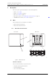


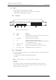

Table Of Contents
- 1 Introduction
- 2 Description
- 3 Safety Instructions
- 4 IP Security
- 5 Installation of the Base Station
- 5.1 Base Station Cabling
- 5.2 Install the Base Station
- 5.2.1 Fix the Mounting Bracket to a Wall
- 5.2.2 Fix the Mounting Bracket to a Ceiling
- 5.2.3 Fix the Mounting Bracket to a Pole or Beam
- 5.2.4 Use the Cable Ducts for IPBS1
- 5.2.5 Connect External Antennas (only IPBS2 and DB1)
- 5.2.6 Secure the Cable
- 5.2.7 Pinning
- 5.2.8 Connect the Base Station Cables
- 5.2.9 Mount the Base Station
- 5.3 Power the Base Station
- 6 Installation of the IPBL
- 7 Configuration
- 7.1 Requirements
- 7.2 Access the GUI
- 7.3 GUI Web Access
- 7.4 Configure the Mobility Master
- 7.5 Configure the Standby Mobility Master
- 7.6 Configure the Pari Master
- 7.7 Configure the Standby Pari Master
- 7.8 Configure the Master
- 7.9 Configure the Standby Master
- 7.10 Plug and Play Configuration
- 7.11 Configure the Radio
- 7.12 Configure Deployment
- 7.13 Add Users
- 8 Operation
- 8.1 General
- 8.1.1 Name the IPBS/IPBL
- 8.1.2 Change User Name and Password
- 8.1.3 Centralized Management of Administrator/Auditor Accounts Using Kerberos
- 8.1.4 Configure Automatic Firmware Update
- 8.1.5 Configure the NTP Settings
- 8.1.6 Configure Logging
- 8.1.7 Configure the HTTP settings
- 8.1.8 Configure the HTTP Client settings
- 8.1.9 SNMP
- 8.1.10 Certificates
- 8.1.11 License
- 8.2 LAN
- 8.3 IP
- 8.4 LDAP
- 8.5 DECT
- 8.5.1 Change System Name and Password
- 8.5.2 Set Subscription Method
- 8.5.3 Configure Authentication Code
- 8.5.4 Select Tones
- 8.5.5 Set Default Language
- 8.5.6 Set Frequency Band
- 8.5.7 Enable Carriers
- 8.5.8 Local R-Key Handling
- 8.5.9 No Transfer on Hangup
- 8.5.10 Configure Coder
- 8.5.11 Secure RTP
- 8.5.12 Configure Supplementary Services
- 8.5.13 Select Mode
- 8.5.14 Set Master Id
- 8.5.15 Enable PARI Function
- 8.5.16 Configure Gatekeeper
- 8.5.17 Registration for Anonymous Devices
- 8.5.18 Select Mobility Master Mode
- 8.5.19 Connect Mobilty Master to other Mobility Master(s)
- 8.5.20 Disconnect Mobilty Master from other Mobility Master(s)
- 8.5.21 Connect Master to a Mobility Master
- 8.5.22 Enable the Radio
- 8.5.23 Enter IP Address to the PARI Master and the Standby PARI Master
- 8.5.24 Multiple Radio Configuration
- 8.5.25 PARI
- 8.5.26 SARI
- 8.5.27 Configure Air Synchronization
- 8.6 VoIP
- 8.7 UNITE
- 8.8 Import and Export a Central Phonebook
- 8.9 Users
- 8.10 Device Overview
- 8.11 DECT Sync
- 8.12 Traffic
- 8.13 Gateway
- 8.14 Backup
- 8.15 Software Upgrade
- 8.15.1 Before Upgrading
- 8.15.2 Upgrading Sequence
- 8.15.3 IPBS/IPBL Upgrade
- 8.15.4 Configuration After Updating the Firmware From Software Version 2.x.x to Later
- 8.15.5 Configuration After Updating the Firmware From Software Version 3.x.x to Later
- 8.15.6 System Upgrade from Software Version 4.x.x to 5.0.x
- 8.16 System Downgrade from software version 5.0.x to 2.x.x, from 4.x.x to 2.x.x and from 3.x.x to 2.x.x
- 8.17 System Downgrade from software version 5.0.x to 3.x.x and 4.x.x to 3.x.x
- 8.18 Update
- 8.19 System Upgrade in System with Mobility Masters
- 8.20 Replacing Master Hardware in Multiple Master System
- 8.21 Diagnostics
- 8.22 Reset
- 8.23 Reset Using the Reset Button
- 8.1 General
- 9 Commissioning
- 10 Troubleshooting
- 11 Related Documents
- Document History
- Appendix A: How to Use the Update Server
- Appendix B: RFP Power Consumption
- Appendix C: Local R-Key Handling
- Appendix D: Database Maintenance
- Appendix E: Load Balancing
- Appendix F: Update Script for Configuration of Kerberos Clients
- Appendix G: Install Certificate in the Web Browser

TD 92579EN
15 February 2012 / Ver. H
Installation and Operation Manual
IP-DECT Base Station & IP-DECT Gateway (software version 5.0.x)
10
2.3 IPBL
The following versions of the IPBL are available:
• IPBL IP-DECT Gateway VAC/VDC (for 110/230 VAC or 48 VDC)
• IPBL IP-DECT Gateway VDC (for 48 VDC)
2.3.1 Overview
Figure 4. Overview of the IPBL
2.3.2 Power Supply
The power supply are located at the rear of the IPBL. The IPBL can be powered using the
following alternatives:
• 110/230 VAC (only IPBL IP-DECT Gateway VAC/VDC)
• 48 VDC
Note: For more information, see 6.3 Power the IPBL on page 40.
Software
The software in the IPBL can be updated by downloading new software without
disconnecting the equipment. The new software is stored in flash memory. See 8.18
Update on page 130 for information.
Pos. Name Function
1 Reset Resets the IPBL, see 8.23 Reset Using the Reset Button on
page 138 for more information.
2 Status LED Indicates the status on the IPBL.
3 Lan 10BASE-T/100BASE-T Ethernet interface.
LAN1 port must be used in the IP-DECT system (LAN2 port
is for administration only).
4 Synchronization Sync ring in and sync ring out interfaces.
5 Reference Reference sync in and reference sync out interfaces.
6 Base station 01-16 ISDN U
PN
DECT base station interfaces.
lan synchronization reference
1 2 ring in ring out in out
base station 01 02 03 04 05 06 07 08
09 10 11 12 13 14 15 16
006
12 3 4 5 6