
User's Manual
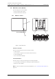
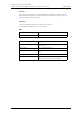
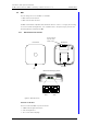
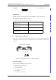
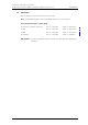
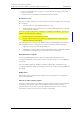
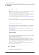
Table Of Contents
- 1 Introduction
- 2 Description
- 3 Safety Instructions
- 4 IP Security
- 5 Installation of the Base Station
- 5.1 Base Station Cabling
- 5.2 Install the Base Station
- 5.2.1 Fix the Mounting Bracket to a Wall
- 5.2.2 Fix the Mounting Bracket to a Ceiling
- 5.2.3 Fix the Mounting Bracket to a Pole or Beam
- 5.2.4 Use the Cable Ducts for IPBS1
- 5.2.5 Connect External Antennas (only IPBS2 and DB1)
- 5.2.6 Secure the Cable
- 5.2.7 Pinning
- 5.2.8 Connect the Base Station Cables
- 5.2.9 Mount the Base Station
- 5.3 Power the Base Station
- 6 Installation of the IPBL
- 7 Configuration
- 7.1 Requirements
- 7.2 Access the GUI
- 7.3 GUI Web Access
- 7.4 Configure the Mobility Master
- 7.5 Configure the Standby Mobility Master
- 7.6 Configure the Pari Master
- 7.7 Configure the Standby Pari Master
- 7.8 Configure the Master
- 7.9 Configure the Standby Master
- 7.10 Plug and Play Configuration
- 7.11 Configure the Radio
- 7.12 Configure Deployment
- 7.13 Add Users
- 8 Operation
- 8.1 General
- 8.1.1 Name the IPBS/IPBL
- 8.1.2 Change User Name and Password
- 8.1.3 Centralized Management of Administrator/Auditor Accounts Using Kerberos
- 8.1.4 Configure Automatic Firmware Update
- 8.1.5 Configure the NTP Settings
- 8.1.6 Configure Logging
- 8.1.7 Configure the HTTP settings
- 8.1.8 Configure the HTTP Client settings
- 8.1.9 SNMP
- 8.1.10 Certificates
- 8.1.11 License
- 8.2 LAN
- 8.3 IP
- 8.4 LDAP
- 8.5 DECT
- 8.5.1 Change System Name and Password
- 8.5.2 Set Subscription Method
- 8.5.3 Configure Authentication Code
- 8.5.4 Select Tones
- 8.5.5 Set Default Language
- 8.5.6 Set Frequency Band
- 8.5.7 Enable Carriers
- 8.5.8 Local R-Key Handling
- 8.5.9 No Transfer on Hangup
- 8.5.10 Configure Coder
- 8.5.11 Secure RTP
- 8.5.12 Configure Supplementary Services
- 8.5.13 Select Mode
- 8.5.14 Set Master Id
- 8.5.15 Enable PARI Function
- 8.5.16 Configure Gatekeeper
- 8.5.17 Registration for Anonymous Devices
- 8.5.18 Select Mobility Master Mode
- 8.5.19 Connect Mobilty Master to other Mobility Master(s)
- 8.5.20 Disconnect Mobilty Master from other Mobility Master(s)
- 8.5.21 Connect Master to a Mobility Master
- 8.5.22 Enable the Radio
- 8.5.23 Enter IP Address to the PARI Master and the Standby PARI Master
- 8.5.24 Multiple Radio Configuration
- 8.5.25 PARI
- 8.5.26 SARI
- 8.5.27 Configure Air Synchronization
- 8.6 VoIP
- 8.7 UNITE
- 8.8 Import and Export a Central Phonebook
- 8.9 Users
- 8.10 Device Overview
- 8.11 DECT Sync
- 8.12 Traffic
- 8.13 Gateway
- 8.14 Backup
- 8.15 Software Upgrade
- 8.15.1 Before Upgrading
- 8.15.2 Upgrading Sequence
- 8.15.3 IPBS/IPBL Upgrade
- 8.15.4 Configuration After Updating the Firmware From Software Version 2.x.x to Later
- 8.15.5 Configuration After Updating the Firmware From Software Version 3.x.x to Later
- 8.15.6 System Upgrade from Software Version 4.x.x to 5.0.x
- 8.16 System Downgrade from software version 5.0.x to 2.x.x, from 4.x.x to 2.x.x and from 3.x.x to 2.x.x
- 8.17 System Downgrade from software version 5.0.x to 3.x.x and 4.x.x to 3.x.x
- 8.18 Update
- 8.19 System Upgrade in System with Mobility Masters
- 8.20 Replacing Master Hardware in Multiple Master System
- 8.21 Diagnostics
- 8.22 Reset
- 8.23 Reset Using the Reset Button
- 8.1 General
- 9 Commissioning
- 10 Troubleshooting
- 11 Related Documents
- Document History
- Appendix A: How to Use the Update Server
- Appendix B: RFP Power Consumption
- Appendix C: Local R-Key Handling
- Appendix D: Database Maintenance
- Appendix E: Load Balancing
- Appendix F: Update Script for Configuration of Kerberos Clients
- Appendix G: Install Certificate in the Web Browser

TD 92579EN
15 February 2012 / Ver. H
Installation and Operation Manual
IP-DECT Base Station & IP-DECT Gateway (software version 5.0.x)
17
DIP Switches
The DIP switches can be found on the back of the DB1, see figure 6 on page 15.
Note: DIP switch 3 and 4 shall be set to ON.
Set DIP switch 1 and 2 to ON or OFF as follows:
2.5.2 DB1 with External Antennas
This section contains the differences between the DB1 with internal antenna and the DB1
with external antennas. For all other information see 2.5.1 DB1 with Internal Antenna on
page 15.
Figure 7. DB1 with MCX connectors for external antennas.
Contents of the Box
The box in which the DB1 is packed contains:
• A DB1 with external antennas.
• A mounting bracket
• An antenna bracket
• Two antenna coaxial cables.
• Two antennas.
• Four screws with wall plugs
Fatal error Solid red. Fatal hardware error.
DIP switch 1: ON
DIP switch 2: ON
Europe frequency
DIP switch 1: OFF
DIP switch 2: ON
China frequency
DIP switch 1: ON
DIP switch 2: OFF
South America frequency
DIP switch 1: OFF
DIP switch 2: OFF
North America frequency
Back view while lying down
MCX connectors