
User's Manual


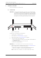

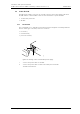

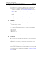
Table Of Contents
- 1 Introduction
- 2 Description
- 3 Safety Instructions
- 4 IP Security
- 5 Installation of the Base Station
- 5.1 Base Station Cabling
- 5.2 Install the Base Station
- 5.2.1 Fix the Mounting Bracket to a Wall
- 5.2.2 Fix the Mounting Bracket to a Ceiling
- 5.2.3 Fix the Mounting Bracket to a Pole or Beam
- 5.2.4 Use the Cable Ducts for IPBS1
- 5.2.5 Connect External Antennas (only IPBS2 and DB1)
- 5.2.6 Secure the Cable
- 5.2.7 Pinning
- 5.2.8 Connect the Base Station Cables
- 5.2.9 Mount the Base Station
- 5.3 Power the Base Station
- 6 Installation of the IPBL
- 7 Configuration
- 7.1 Requirements
- 7.2 Access the GUI
- 7.3 GUI Web Access
- 7.4 Configure the Mobility Master
- 7.5 Configure the Standby Mobility Master
- 7.6 Configure the Pari Master
- 7.7 Configure the Standby Pari Master
- 7.8 Configure the Master
- 7.9 Configure the Standby Master
- 7.10 Plug and Play Configuration
- 7.11 Configure the Radio
- 7.12 Configure Deployment
- 7.13 Add Users
- 8 Operation
- 8.1 General
- 8.1.1 Name the IPBS/IPBL
- 8.1.2 Change User Name and Password
- 8.1.3 Centralized Management of Administrator/Auditor Accounts Using Kerberos
- 8.1.4 Configure Automatic Firmware Update
- 8.1.5 Configure the NTP Settings
- 8.1.6 Configure Logging
- 8.1.7 Configure the HTTP settings
- 8.1.8 Configure the HTTP Client settings
- 8.1.9 SNMP
- 8.1.10 Certificates
- 8.1.11 License
- 8.2 LAN
- 8.3 IP
- 8.4 LDAP
- 8.5 DECT
- 8.5.1 Change System Name and Password
- 8.5.2 Set Subscription Method
- 8.5.3 Configure Authentication Code
- 8.5.4 Select Tones
- 8.5.5 Set Default Language
- 8.5.6 Set Frequency Band
- 8.5.7 Enable Carriers
- 8.5.8 Local R-Key Handling
- 8.5.9 No Transfer on Hangup
- 8.5.10 Configure Coder
- 8.5.11 Secure RTP
- 8.5.12 Configure Supplementary Services
- 8.5.13 Select Mode
- 8.5.14 Set Master Id
- 8.5.15 Enable PARI Function
- 8.5.16 Configure Gatekeeper
- 8.5.17 Registration for Anonymous Devices
- 8.5.18 Select Mobility Master Mode
- 8.5.19 Connect Mobilty Master to other Mobility Master(s)
- 8.5.20 Disconnect Mobilty Master from other Mobility Master(s)
- 8.5.21 Connect Master to a Mobility Master
- 8.5.22 Enable the Radio
- 8.5.23 Enter IP Address to the PARI Master and the Standby PARI Master
- 8.5.24 Multiple Radio Configuration
- 8.5.25 PARI
- 8.5.26 SARI
- 8.5.27 Configure Air Synchronization
- 8.6 VoIP
- 8.7 UNITE
- 8.8 Import and Export a Central Phonebook
- 8.9 Users
- 8.10 Device Overview
- 8.11 DECT Sync
- 8.12 Traffic
- 8.13 Gateway
- 8.14 Backup
- 8.15 Software Upgrade
- 8.15.1 Before Upgrading
- 8.15.2 Upgrading Sequence
- 8.15.3 IPBS/IPBL Upgrade
- 8.15.4 Configuration After Updating the Firmware From Software Version 2.x.x to Later
- 8.15.5 Configuration After Updating the Firmware From Software Version 3.x.x to Later
- 8.15.6 System Upgrade from Software Version 4.x.x to 5.0.x
- 8.16 System Downgrade from software version 5.0.x to 2.x.x, from 4.x.x to 2.x.x and from 3.x.x to 2.x.x
- 8.17 System Downgrade from software version 5.0.x to 3.x.x and 4.x.x to 3.x.x
- 8.18 Update
- 8.19 System Upgrade in System with Mobility Masters
- 8.20 Replacing Master Hardware in Multiple Master System
- 8.21 Diagnostics
- 8.22 Reset
- 8.23 Reset Using the Reset Button
- 8.1 General
- 9 Commissioning
- 10 Troubleshooting
- 11 Related Documents
- Document History
- Appendix A: How to Use the Update Server
- Appendix B: RFP Power Consumption
- Appendix C: Local R-Key Handling
- Appendix D: Database Maintenance
- Appendix E: Load Balancing
- Appendix F: Update Script for Configuration of Kerberos Clients
- Appendix G: Install Certificate in the Web Browser

TD 92579EN
15 February 2012 / Ver. H
Installation and Operation Manual
IP-DECT Base Station & IP-DECT Gateway (software version 5.0.x)
36
6 Installation of the IPBL
This section describes how to install the IPBL.
6.1 Install the IPBL
IMPORTANT: To keep the same functionality of the system, do not mix different RFPs,
Core (KRCNB 201) with Worf (KRCNB 30x and BS3x0), on the same IPBL.
The reason this will not work is prolonged preamle is supported by Worf
RFPs but not by Core RFPs. When the handset receive capacity information
from the RFPs, including prolonged preamble and multicast, it assumes
that all RFPs are of the same type as the first RFP it receives data from.
Figure 16. Install the IPBL
The main steps of the installation is described below:
1 Install the IPBL in a standard 19’’ rack.
2 Pin the cables, see 6.2 Pin the IPBL Cable on page 38.
3 Attach the power cable, see 6.3 Power the IPBL on page 40.
4 Connect the cables in the following order:
• Ethernet cable (A) LAN1 port must be used in the IP-DECT system (LAN2 port is
for administration only).
• Synchronization cable (ring sync, reference sync) (B)
• Base station cable (RFP cable) (C)
IMPORTANT: The connected RFPs must not be connected to protective earth.
5 Monitor the total current consumption from the GUI. See 8.21.9 Environment on
page 137. Make sure it not exceeds the following values:
• Max current consumption is 1,9/0,9 A when supplied with 110/230 VAC.
• Max current consumption is 5,2 A when supplied with 48 VDC.
Note: The IPBL current consumption is 0,3 A and is included in max current
Figure 12.
lan synchronization reference
1 2 ring in ring out in out
base station 01 02 03 04 05 06 07 08
09 10 11 12 13 14 15 16
035
{
{
{
A
B C