
User's Manual
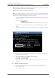


Table Of Contents
- 1 Introduction
- 2 Description
- 3 Safety Instructions
- 4 IP Security
- 5 Installation of the Base Station
- 5.1 Base Station Cabling
- 5.2 Install the Base Station
- 5.2.1 Fix the Mounting Bracket to a Wall
- 5.2.2 Fix the Mounting Bracket to a Ceiling
- 5.2.3 Fix the Mounting Bracket to a Pole or Beam
- 5.2.4 Use the Cable Ducts for IPBS1
- 5.2.5 Connect External Antennas (only IPBS2 and DB1)
- 5.2.6 Secure the Cable
- 5.2.7 Pinning
- 5.2.8 Connect the Base Station Cables
- 5.2.9 Mount the Base Station
- 5.3 Power the Base Station
- 6 Installation of the IPBL
- 7 Configuration
- 7.1 Requirements
- 7.2 Access the GUI
- 7.3 GUI Web Access
- 7.4 Configure the Mobility Master
- 7.5 Configure the Standby Mobility Master
- 7.6 Configure the Pari Master
- 7.7 Configure the Standby Pari Master
- 7.8 Configure the Master
- 7.9 Configure the Standby Master
- 7.10 Plug and Play Configuration
- 7.11 Configure the Radio
- 7.12 Configure Deployment
- 7.13 Add Users
- 8 Operation
- 8.1 General
- 8.1.1 Name the IPBS/IPBL
- 8.1.2 Change User Name and Password
- 8.1.3 Centralized Management of Administrator/Auditor Accounts Using Kerberos
- 8.1.4 Configure Automatic Firmware Update
- 8.1.5 Configure the NTP Settings
- 8.1.6 Configure Logging
- 8.1.7 Configure the HTTP settings
- 8.1.8 Configure the HTTP Client settings
- 8.1.9 SNMP
- 8.1.10 Certificates
- 8.1.11 License
- 8.2 LAN
- 8.3 IP
- 8.4 LDAP
- 8.5 DECT
- 8.5.1 Change System Name and Password
- 8.5.2 Set Subscription Method
- 8.5.3 Configure Authentication Code
- 8.5.4 Select Tones
- 8.5.5 Set Default Language
- 8.5.6 Set Frequency Band
- 8.5.7 Enable Carriers
- 8.5.8 Local R-Key Handling
- 8.5.9 No Transfer on Hangup
- 8.5.10 Configure Coder
- 8.5.11 Secure RTP
- 8.5.12 Configure Supplementary Services
- 8.5.13 Select Mode
- 8.5.14 Set Master Id
- 8.5.15 Enable PARI Function
- 8.5.16 Configure Gatekeeper
- 8.5.17 Registration for Anonymous Devices
- 8.5.18 Select Mobility Master Mode
- 8.5.19 Connect Mobilty Master to other Mobility Master(s)
- 8.5.20 Disconnect Mobilty Master from other Mobility Master(s)
- 8.5.21 Connect Master to a Mobility Master
- 8.5.22 Enable the Radio
- 8.5.23 Enter IP Address to the PARI Master and the Standby PARI Master
- 8.5.24 Multiple Radio Configuration
- 8.5.25 PARI
- 8.5.26 SARI
- 8.5.27 Configure Air Synchronization
- 8.6 VoIP
- 8.7 UNITE
- 8.8 Import and Export a Central Phonebook
- 8.9 Users
- 8.10 Device Overview
- 8.11 DECT Sync
- 8.12 Traffic
- 8.13 Gateway
- 8.14 Backup
- 8.15 Software Upgrade
- 8.15.1 Before Upgrading
- 8.15.2 Upgrading Sequence
- 8.15.3 IPBS/IPBL Upgrade
- 8.15.4 Configuration After Updating the Firmware From Software Version 2.x.x to Later
- 8.15.5 Configuration After Updating the Firmware From Software Version 3.x.x to Later
- 8.15.6 System Upgrade from Software Version 4.x.x to 5.0.x
- 8.16 System Downgrade from software version 5.0.x to 2.x.x, from 4.x.x to 2.x.x and from 3.x.x to 2.x.x
- 8.17 System Downgrade from software version 5.0.x to 3.x.x and 4.x.x to 3.x.x
- 8.18 Update
- 8.19 System Upgrade in System with Mobility Masters
- 8.20 Replacing Master Hardware in Multiple Master System
- 8.21 Diagnostics
- 8.22 Reset
- 8.23 Reset Using the Reset Button
- 8.1 General
- 9 Commissioning
- 10 Troubleshooting
- 11 Related Documents
- Document History
- Appendix A: How to Use the Update Server
- Appendix B: RFP Power Consumption
- Appendix C: Local R-Key Handling
- Appendix D: Database Maintenance
- Appendix E: Load Balancing
- Appendix F: Update Script for Configuration of Kerberos Clients
- Appendix G: Install Certificate in the Web Browser

TD 92579EN
15 February 2012 / Ver. H
Installation and Operation Manual
IP-DECT Base Station & IP-DECT Gateway (software version 5.0.x)
43
Note: If the GUI cannot be accessed with Internet Explorer 8 or newer, check that the TLS
1.0 option is activated in the web browser under menu Tools > Internet Option >
Advanced > Use TLS 1.0.
7.2.1 Determine the IP Address
The factory setting of the DHCP mode for the LAN1 port is "automatic", at first power up
it will act as a DHCP client. If the network has a DHCP server, it will assign an IP address to
the IPBS/IPBL. If there is no DHCP server in the network, the IPBS/IPBL can be assigned a
predefined IP address. The factory setting of the DHCP mode is to the fixed IP address
192.168.0.1, see 8.2.1 Set 8.2.1 Set DHCP Mode on page 79.
Note: After the first startup the DHCP mode should be changed from "automatic" to
either "client" or "off", see
8.2.1 Set DHCP Mode on page 79.
This section describes how to determine the dynamically allocated IP address. The address
is used to access the IPBS/IPBL using a web browser. Two methods are described:
• In a Network without a DHCP Server on page 43.
• In a Network with a DHCP Server on page 43.
In a Network without a DHCP Server
If the network does not have a DHCP server, and the DHCP mode is set to "automatic"
(factory default), follow the steps below.
Note: If the IPBS/IPBL has been used before, it must be restored to factory default settings
by performing a long hardware reset, see
8.23 Reset Using the Reset Button on page 138.
1 Connect an Ethernet cable between the IPBS/IPBL and the computer.
NOTE: For IPBS, a power adapter must be used.
NOTE: For IPBL, make sure to use the LAN1 port.
2 Ensure that the computer has an IP address within the same IP address range as the
IPBS/IPBL (192.168.0.1).
3 Perform a hardware reset by shortly pressing the reset button.
The IPBS/IPBL will be assigned the IP address 192.168.0.1 and the netmask
255.255.255.0.
4 Enter http://192.168.0.1 in the browser to access the IPBS/IPBL GUI.
5 After the first startup, do the following:
On the IPBS: Select LAN1 > DHCP
On the IPBL: Select LAN1 > DHCP
6 In Mode drop-down list, change the DHCP mode from "automatic" to "disabled".
In a Network with a DHCP Server
If the network has a DHCP server the IP address is determined following the steps below.
The IPBS’s MAC address can be found on the label on the box and on the label on the
backside. The IPBL’s MAC address can be found on the label on the box. The hexadecimal
numbers (xx-xx-xx-xx-xx-xx) represent the MAC address.
Note: Make sure to use the LAN1 port for the IPBL.