
User's Manual

TD 93021US Rev A
10 FEB 2014 / Ver A 95
Installation Guide
teleCARE IP
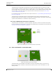
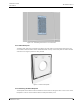
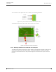
Figure 123. Cable of the pull cord module with the 4-pole connector
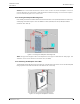
Plug in the connection terminal to the appropriate 4-pin connector of the pull cord module (active =
room bus connector, passive = passive bus connector).
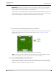
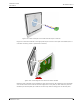
Figure 124. Connecting the room bus to the switch module
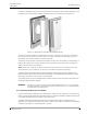
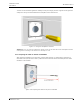
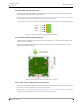
Mount the switch module on the backplate by first position the two latch fasteners of the backplate
over the two teeth on the inside of the lower edge of the cover plate (1). Next rotate the pull cord
module up to the backplate (2) so that the screws line up with the fixing posts on the back plate.