
User's Manual


TD 93021US Rev A
10 FEB 2014 / Ver A 147
Installation Guide
teleCARE IP
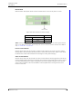
Master / Slave Mode DIP Switch Settings
With DIP switch SW2 (8) the master / slave mode of the NILF can be set.
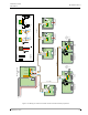
Figure 202. Master / Slave DIP switch settings
A master/slave configuration can be used to extend the range of the LF field (when master and slave
use same ID) or to synchronize LF transmissions between two beacons when there is an overlap in the
LF fields (when master and slave use different IDs).
Refer to “NILF ID” on page 145 for setting the ID of the slave NILF.
Refer to “Beacon Mode” on page 148 for setting the mode of the slave NILF.
Refer to “Output Power and Transmission Rate DIP Switch Settings” on page 146 to set the
output power of the slave NILF. Note that the transmission rate is decided by the master
synchronization, and setting this option on the slave will have no effect.
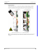
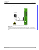
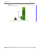
Master / Slave Beacon Interconnection
Connector J2 pin1 (SYNC) and pin 2 (GND) are the interconnection pins used for beacons operating in
master / slave mode. Interconnect the “Sync / GND” connections between the master and slave
beacon as depicted below.
Figure 203. NILF master / slave interconnection
Note: Minimum recommended cable requirements (twisted pair) for example CAT5. Length
< 100m.
NILF Master / Slave Settings
SW2 (8) Mode
Off = 0 Master
On = 1 Slave
SW 2
Master / Slave
Master
Slave