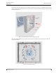
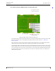
Installation Guide teleCARE IP TD 93021US Rev A Place the housing over the back box so that the long sides are at the top and bottom. Pass the heads of the screws through the appropriate “key-hole” slots (2) in the base of the housing, as shown in the following illustration: Figure 18. Positioning the screws in the keyhole slots Turn the housing (3) until the long sides are horizontal, then tighten the back box fixing screws to secure the housing. Figure 19.
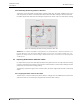
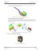
Installation Guide teleCARE IP TD 93021US Rev A 5.2.10 Mounting the Housing without a Back box The housing can be mounted on a flat surface, without a back box, using four suitable screws in the outer fixing holes, as shown in the illustration below. When the NIRC housing is without a back box the cables should enter and leave the housing through the two knock-outs in the sides of the housing. Cable Figure 20.
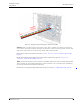
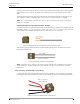
Installation Guide teleCARE IP TD 93021US Rev A Figure 21. Stripping and positioning the cables for the NIRC Caution: Each room bus requires four wires. If the cable contains more than four wires the excess wires should be carefully stowed in the back box, away from the printed circuit board and other components to avoid electrical faults and safety problems. Details of the room bus connections are given in 5.4.1, 4-Pole Connector Terminal (NICT-4AA), page 31.
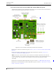
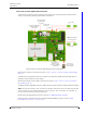
Installation Guide teleCARE IP TD 93021US Rev A 5.3.2 Room Controller PCB Connections (NIRC-GMS and NIRC-WMS with Speech) The electrical connections on the component side of the IP room controller printed circuit board are shown in the following drawing of the NIRC circuit board. LED Lamp Board Through-Board Connectors (only applicable to corridor lamp version) External Corridor Lamp Outputs (Max.
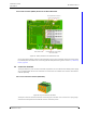
Installation Guide teleCARE IP TD 93021US Rev A 5.3.3 IP Room Controller (NIRC) Printed Circuit Board Back View Through-Board Connection Holes for the LED Lamp MAC address label Product label with part number and serial number Figure 23. NIRC printed circuit board back view On the back of the printed circuit board there are four sets of through-board connection holes for LED lamp boards. Details of for connecting the LED lamp boards are given in section 5.6, LED Lamp Boards, page 43.
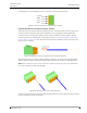
Installation Guide teleCARE IP TD 93021US Rev A 5.3.4 Room Controller (NIRC3) PCB Connections The electrical connections on the component side of the room controller printed circuit board are shown in the following drawing of the NIRC3 circuit board. LED Lamp Board Through-Board Connectors Transceiver piggyback (NIRX) extension connectors Room bus 0 2 x USB 2.
Installation Guide teleCARE IP TD 93021US Rev A 5.3.5 Room Controller (NIRC3) Printed Circuit Board Back View Through-Board Connection Holes for the LED Lamp NIRC3 MAC address label Product label with part number and serial number Figure 25. NIRC3 printed circuit board back view On the back of the NIRC3 printed circuit board there are four sets of through-board connection holes for LED lamp boards. Details of for connecting the LED lamp boards are given in section 5.6, LED Lamp Boards, page 43. 5.
Installation Guide teleCARE IP TD 93021US Rev A The designation of the required four wires is as shown in the following illustration. +5.5Vdc DATA VOICE GND Figure 27. 4-pole connector terminal with the room bus Preparing the Wires for the 4-pole Connector Terminal The 4-pole connector terminal has four terminals with two connection points at each terminal. Each connection point accepts one solid wire of maximum wire size 20 gauge (0.5mm²) (0.8mmØ).
Installation Guide teleCARE IP TD 93021US Rev A Four wires are required for the room bus, passive bus and light relay outputs, so repeat the above illustrated procedure on the remaining three wires. Figure 30. Connector terminal complete with four wires Disconnecting a Wire from the Connector Terminal First carefully place the point of a small screw driver (point approximately 0.1in (2.
Installation Guide teleCARE IP TD 93021US Rev A The 2-pole connector terminal is used for connecting the 24Vdc power supply when a separate power supply is used. It is also used for the 24Vdc power supply from the room controller to the corridor lamp. The 2-pole terminal connector has two screw terminals. Each terminal accepts one wire (up to wire size 14 gauge (1.5mm²) (1.4mmØ) or two wires (each up to 18 gauge (1mm²) (1.15mmØ).
Installation Guide teleCARE IP TD 93021US Rev A Note: The maximum size of each wire when two wires are inserted in one screw terminal of the 2-pole connector terminal is 18 gauge (1 mm²) (1.15 mmØ). 5.