
User's Manual

TD 93021US Rev A
10 FEB 2014 / Ver A 34
Installation Guide
teleCARE IP
The 2-pole connector terminal is used for connecting the 24Vdc power supply when a separate power
supply is used. It is also used for the 24Vdc power supply from the room controller to the corridor
lamp.
The 2-pole terminal connector has two screw terminals. Each terminal accepts one wire (up to wire
size 14 gauge (1.5mm²) (1.4mmØ) or two wires (each up to 18 gauge (1mm²) (1.15mmØ).
Note: The recommended maximum wire size for the teleCARE power supply is 18 gauge
(1mm²) (1.15mmØ).
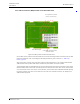
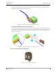
Preparing the Wires for the 2-pole Connector Terminal
To connect the wires first pull the wires through the housing leaving a length of 6in (150mm) free, as
described in section 5.3, Preparing the Room Bus and Power Cables on page 26. Then strip 0.25
inch (6.5mm) of the insulation from the end of each wire which is to be connected.
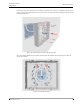
Figure 33. Stripping the wires for insertion in the connection point
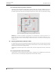
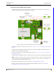
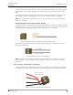
After stripping the wire insert the wire in the appropriate opening of the connector terminal and
tighten the terminal screw.
Figure 34. 2-pole connector terminal wiring
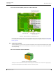
Note: If stranded wire is used for the power supply cabling then a suitable ferrule (barrel
outer diameter > 0.04in (1mm) should be used over the wire cores to ensure a reliable
connection.
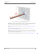
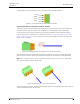
2-Pole Connector Terminal with Looped Wiring
In cases where the power supply cable loops from room controller to room controller, the incoming
and outgoing wires are connected in the same screw terminal, as shown in the following illustration:
Figure 35. Connector terminal with looped wiring
0Vdc (GND)
+Vdc in / +Vdc out
Max. 2 x 18 gauge
1mm² (0·8mmØ)