
User's Manual


TD 93021US Rev A
10 FEB 2014 / Ver A 35
Installation Guide
teleCARE IP
Note: The maximum size of each wire when two wires are inserted in one screw terminal of
the 2-pole connector terminal is 18 gauge (1 mm²) (1.15 mmØ).
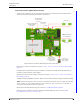
5.5 Connecting the IP Room Controller Printed Circuit Board
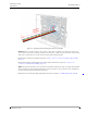
When preparing the wiring for connecting the printed circuit board of the IP room controller make
sure that the power supply wires and the room bus wires are stripped of the cable outer jacket and
that the wires are long enough, as described in section 5.3, Preparing the Room Bus and Power
Cables on page 26.
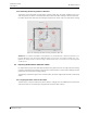
It is best to arrange the wires and cables neatly and securely inside the housing. The power wires and
the room buses should be guided around sides of the room controller housing and held in place by the
wire holding clips.
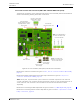
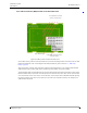
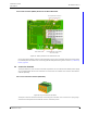
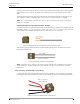
The instructions will include the procedures for both the NIRC and the NIRC3 room controller.
NIRC
NIRC3