
User's Manual

TD 93021US Rev A
10 FEB 2014 / Ver A 28
Installation Guide
teleCARE IP
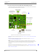
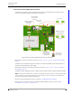
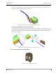
5.3.2 Room Controller PCB Connections (NIRC-GMS and NIRC-WMS with Speech)
The electrical connections on the component side of the IP room controller printed circuit board are
shown in the following drawing of the NIRC circuit board.
Figure 22. IP room controller (with speech) PCB electrical connections
Details of the room bus connections are given in 5.4.1, 4-Pole Connector Terminal (NICT-4AA),
page 31.
Details of the 24Vdc power supply and corridor lamp connections are given in 5.4.2, 2-Pole
Connector Terminal (NICT-2BA), page 33
Note: The 6-pole, 4-pole and the 2-pole connector terminals required for the external
corridor LED lamps, the room bus and the 24V power supply are not supplied with the IP
room controller. The connectors are available as accessories and must be ordered
separately.
Details of for connecting the LED lamp boards are given in section 5.6, LED Lamp Boards, page 43.
Details of for connecting external corridor lamp LEDs are given in section 5.6.4, External Corridor
Lamp Connections, page 47
PoE Extension
Connector (Future use)
LED Lamp Board
Through-Board Connectors
(only applicable to corridor
lamp version)
Room Bus 2
Room Bus 1
Room Bus 0
RJ 45
LAN Connector
Note: The 24Vdc power
outputs are only to be used
for the corridor lamps!
Buzzer
External Corridor Lamp
Outputs (Max. load per
connection: 60mA)
2 x 24Vdc OUT
Corridor Lamps
Power Supply.
24Vdc IN
Room Controller
Power Supply
Note: The combined load of
the three room buses must
not exceed 750mA!