
User's Manual

TD 93021US Rev A
10 FEB 2014 / Ver A 30
Installation Guide
teleCARE IP
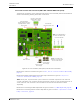
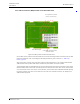
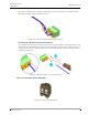
5.3.4 Room Controller (NIRC3) PCB Connections
The electrical connections on the component side of the room controller printed circuit board are
shown in the following drawing of the NIRC3 circuit board.
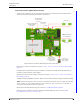
Figure 24. Room controller (NIRC3) PCB electrical connections
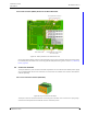
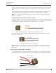
Details of the room bus connections are given in 5.4.1, 4-Pole Connector Terminal (NICT-4AA),
page 31.
The NIRC3 can be powered directly from a Power over Ethernet (PoE 802.3af or 802.3at) switch or
through an external 24V DC power supply.
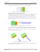
Details of the 24V DC power supply connections are given in 5.4.2, 2-Pole Connector Terminal
(NICT-2BA), page 33
The NIRC3 has two USB2.0HS host ports. Will be used in a future release to support WiFi functionality.
Note: The 4-pole and the 2-pole connector terminals required for the room bus and the 24V
power supply are not supplied with the room controller. The connectors are available as
accessories and must be ordered separately.
Details of the LED lamp boards are given in section 5.6, LED Lamp Boards, page 43.
Details on how to install the transceiver piggyback module (NIRX) are given in section “NIRX
teleCARE IP Transceiver” on page 172.
RJ 45
LAN Connector
with Power over
Ethernet capability
PoE 802.3af
2 x USB 2.0HS
Host Ports
24V DC IN
Room Controller
Power Supply
Note: rated 500mA
(room bus power)
LED Lamp Board
Through-Board
Connectors
Transceiver piggyback
(NIRX) extension
connectors
Voice piggyback (NIVP)
extension connectors
Room bus
01
Room bus
23
NIRC3
Buzzer