
User's Manual

TD 93021US Rev A
10 FEB 2014 / Ver A 32
Installation Guide
teleCARE IP
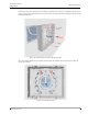
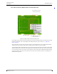
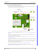
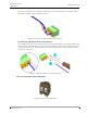
The designation of the required four wires is as shown in the following illustration.
Figure 27. 4-pole connector terminal with the room bus
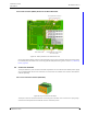
Preparing the Wires for the 4-pole Connector Terminal
The 4-pole connector terminal has four terminals with two connection points at each terminal. Each
connection point accepts one solid wire of maximum wire size 20 gauge (0.5mm²) (0.8mmØ).
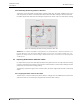
To connect the wires first strip the jacket from the cables and pull the wires through the housing
leaving a length of 6in (150mm) free, as described in section 5.3, Preparing the Room Bus and
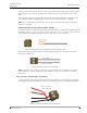
Power Cables on page 26. Then strip 0.25in (6.5mm) of the insulation from the end of each wire
which is to be connected.
Figure 28. Stripping the wires for insertion in the connection terminal
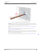
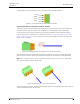
After stripping the wire to expose 0.25in (6.5mm) of conductor, insert the wire in the appropriate
opening of the connection point by pressing the wire firmly into the terminal, as illustrated below.
Note: Each connection point in the connector terminal accepts only one wire. Maximum
wire size 24 gauge (0.5mm²) (0.8mmØ).
Figure 29. Inserting a wire in the connection point
Check that a good connection has been made by gently pulling on the wire after it has been inserted.
The wire should stay fixed in the terminal.
+5.5Vdc
DATA
VOICE
GND