
User's Manual


TD 93021US Rev A
10 FEB 2014 / Ver A 53
Installation Guide
teleCARE IP
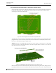
5.7.5 4-Pole Connector Terminal
Figure 62. 4-pole connector terminal
The 4-pole connector terminal is used for connecting the room bus. It has a screw-less “spring-cage”
connection technique and each terminal has two connection points.
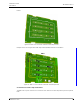
The designation of the required four wires is as shown in the following illustration.
Figure 63. 4-pole connector terminal with the room bus
Preparing the wires and connecting the 4-pole connection terminal is described in section 5.4.1, 4-
Pole Connector Terminal (NICT-4AA) on page 31.
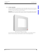
5.7.6 2-Pole Connector Terminal
Figure 64. 2-pole connector terminal
The 2-pole connector terminal is used for connecting the 24Vdc power supply from the room
controller to the corridor lamp. The designation of the required power supply wires is as shown in the
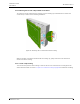
following illustration.
Figure 65. 2-pole connector terminal wiring
5.5 Vdc
DATA
VOICE
GND
0V (GND)
+V in