
User's Manual


TD 93021US Rev A
10 FEB 2014 / Ver A 54
Installation Guide
teleCARE IP
Preparing the wires and connecting the 2-pole connection terminal is described in section 5.4.2, 2-
Pole Connector Terminal (NICT-2BA) on page 33.
5.7.7 Connecting the Corridor Lamp Printed Circuit Board
When preparing the wiring for connecting the printed circuit board of the corridor lamp make sure
that the power supply wires and the room bus wires are stripped of the cable outer jacket and that the
wires are long enough, as described in section 5.3, Preparing the Room Bus and Power Cables
on page 26.
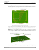
It is best to arrange the wires and cables neatly and securely inside the housing. The power wires and
the room bus should be guided around the sides of the corridor lamp housing and held in place by the
wire holding clips.
Figure 66. Connecting the corridor lamp
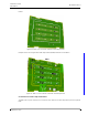
5.7.8 LED Lamp Boards for the Corridor Lamp
Note: The LED lamp boards are not delivered as part of the corridor lamp and therefore,
must be ordered separately.
The LED lamp board contains four high intensity LED lamps which are used for the signaling of various
types of calls including staff presence and system faults.
The three pins in the back side of the LED board are used to connect the LED lamp board through
holes in the back side of the corridor lamp printed circuit board. The corridor lamp accepts up to four
LED lamp boards.
The LED lamp connection points are labeled LED0, LED1, LED2 and LED3. Any color LED board can be
plugged into any of the connection points on the IP room controller. The appropriate position of the
LED color is determined during the system setup.
The LED lamp board is available in five colors: red, green, yellow, white and blue. The functions of the
LEDs are determined by the system setup.
Use the Wire
Holding Clip
Use the Wire
Holding Clip