
User's Manual


TD 93021US Rev A
10 FEB 2014 / Ver A 101
Installation Guide
teleCARE IP
• The Auxiliary Monitoring circuits are power limited to 5.5Vdc at 0.6mA.
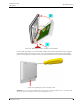
Caution: The tamper alarm function is not possible when the spacer is used.
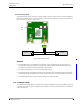
6.14.1 Card Reader Electrical Connections
The NICR has two connectors consisting of the room bus and the auxiliary connections. It is an “active
peripheral” therefore it must be connected to one of the three room buses of a teleCARE IP room
controller by the 4-pole room bus connector (see 6.4.1, 4-Pole Connector Terminal on page 65).
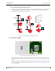
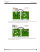
Figure 132. Card reader electrical connections
Note: The two 4-pole connector terminals required for the room bus and the auxiliary
connections are not supplied with the card reader. They are available as accessories and
must be ordered separately.
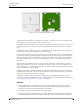
NICR Room Bus Address
The NICR can be connected to any of the room buses of the IP room controller, in the same way as all
other teleCARE IP peripherals. Each room bus supports one NICR and the address of the NICR is fixed
at 6.
It is highly recommended to place the NICR as the first teleCARE IP peripheral on the room bus, closest
to the room controller, to minimize the risk of a voltage drop on the room bus power lines caused by
4-Pole
Connector
for Room Bus
Tamper
Switch
Auxiliary
Connections