
User's Manual


TD 93021US Rev A
10 FEB 2014 / Ver A 93
Installation Guide
teleCARE IP
6.12.8 Room Bus Electrical Connections
The NIPC2 GAA and NIPC2 WAA are active teleCARE IP peripherals which must be connected to the
4-pin room bus connector on the switch module.
Refer to section 6.4.2, Preparing the Wires for the 4-pole Connector Terminal on page 66). in order to
correctly strip the cable and prepare the wires for the 4-pole connector.
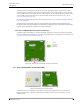
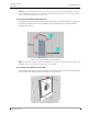
The connections of the room bus wires in the 4-pole connector are shown in the following illustration.
Figure 119. 4-pole connector terminal with the room bus
6.12.9 Room Bus Address DIP Switch Settings
The NIPC2 (GAA and WAA) uses one of the first four addresses (0, 1, 2 and 3) of the room bus. The
address is set by a DIP switch.
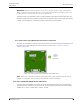
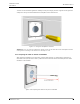
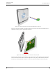
The illustration below shows the location of the room bus connector and the location of the DIP
switch with the address settings.
Figure 120. Room bus connector and DIP switch location
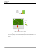
6.12.10 Passive Pull Cord Module Electrical Connections
The NIPC2 GAP and NIPC2 WAP are passive teleCARE IP peripherals which must be connected to the
passive bus of a door side module or a toilet cancel module.
Refer to section 6.4.2, Preparing the Wires for the 4-pole Connector Terminal on page 66). in order to
correctly strip the cable and prepare the wires for the 4-pole connector.
5.5Vdc
DATA
VOICE
GND
4-Pole Connector
for the Room Bus
DIP
Switch
address
settings