
User's Manual


TD 93021US Rev A
10 FEB 2014 / Ver A 64
Installation Guide
teleCARE IP
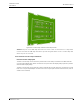
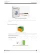
Figure 70. Surface mounting spacer
Note: When no back box is available it is best to use the screw holes furthest from the
center to mount the spacer on a flat surface.
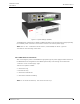
6.3.3 Mounting the Spacer on a Back Box
To mount the spacer on a back box the mounting screws in the back box should not be removed but
partially unscrewed to extend at least 0.2in (5mm) above the wall surface.
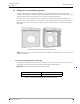
The spacer should be placed over the back box so that the side marked “TOP” will be up. Then pass
the heads of the screws through the eyes of the “key-hole” slots in the base of the spacer (1). The
spacer must then be turned until the side marked “TOP” is uppermost (2) and finally the back box
screws should be tightened.
Figure 71. Mounting the spacer on the back box
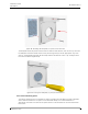
6.4 Switch Module Electrical Connections
It is important to ensure that a minimum of 14in (35cm) of free cable is pulled out of the back box at
every location where teleCARE peripherals are to be installed.