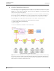
System Description teleCARE IP 9.4 TD 93025US Principle of the Wireless Infrastructure In an environment consisting mainly of wireless devices, a full wireless infrastructure can be achieved using a wireless gateway (NIRC3 + NUREP) in combination with wireless repeaters (NUREP), To create a wireless gateway, a wireless repeater (NUREP) is connected via a USB cable to a room controller (NIRC3). The wireless gateway is located at a location with access to the IP-network.
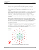
System Description teleCARE IP 9.5 TD 93025US Wireless Infrastructure RF Planning Considerations A wireless device must be seen at all possible locations. To avoid an overload of RF messages from being sent to the wireless server, a message should (preferably) only end up at one wireless gateway segment, which consists of multiple wireless repeaters and a gateway.
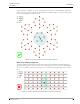
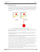
System Description teleCARE IP TD 93025US Setup a wireless segment in such a way that the repeaters are surrounding the gateway. This will result in wireless gateways being mounted further apart, therefore reducing the risk of overloading the wireless server. Figure 50. Correctly mounted wireless gateway segments Multi-storey building configuration A similar approach should be considered for multi-storey buildings.
System Description teleCARE IP TD 93025US Spreading the repeaters connected to a single gateway across multiple floors will result in less traffic being forwarded towards the wireless server. Figure 52. Correctly mounted wireless gateway segments Note: Be aware that walls and floor/ceilings will reduce the range of RF transmissions. So make sure that the repeaters in a subnet are able to receive messages from the next and the previous repeater/gateway in the chain. 9 May 2019 / Ver.
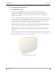
System Description teleCARE IP 9.6 TD 93025US teleCARE IP Wireless Components 9.6.1 NUREP Wireless Repeater The wireless repeater (NUREP) is a surface (wall) mounted teleCARE IP wireless infrastructure building-block. Wireless repeaters receive the signals from the wireless modules from residents and all the wireless modules in the resident room. Wireless repeaters also retransmit these signals to the central equipment (wireless gateway), via other wireless repeaters.
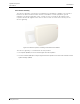
System Description teleCARE IP TD 93025US 9.6.2 Wireless Gateway The wireless gateway, consisting of a combination of the NIRC3 + NUREP is the interface between the wireless infrastructure and the teleCARE IP central equipment (system manager). The wireless gateway is the central receiver receiving the RF signals of the repeaters and the RF signals of the wireless devices that are in the direct vicinity of the wireless gateway. Figure 54.
System Description teleCARE IP TD 93025US 9.6.3 NUWBM3 Wireless Active Bedside Module The wireless bedside module (NUWBM3-HU) is a wall mounted teleCARE IP wireless peripheral containing a 916 - 921 MHz RF transceiver. It comes with a spacer and installation kit for surface mounting. The NUWBM3 has 3 customizable function buttons with configurable color button inserts and a magnetic SafeConnect socket. Each button has a customizable color-matching LED that lights up when pressed, for reassurance.
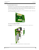
System Description teleCARE IP TD 93025US 9.6.4 NIRX teleCARE IP Transceiver The NIRX transceiver is a printed circuit module which is piggy back mounted on the NIRC3 room controller and the NIFX fixed transceiver. Mounting the NIRX will add wireless functionality to the NIRC3 room controller and the fixed transceiver. Optionally the NIRX can also be mounted on the NILF location beacon for actively monitoring the state of the NILF, such as tamper and low battery alarm conditions.
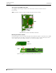
System Description teleCARE IP TD 93025US The Location of the NIRX on the NITX The piggyback mounting the NIRX on the NIFX room controller enables wireless functionality. Note: The NIFX is delivered with an NIRX mounted from the factory. NIRX NIFX Figure 58. The Location of the NIRX on the NITX Mounting the NIRX on the NILF If monitoring the LF beacon (NILF) through an RF heartbeat signal is required then the NIRX must be mounted on the NILF circuit board.
System Description teleCARE IP TD 93025US 9.6.5 NIFX Fixed Transceiver The NIFX series fixed transceiver is a wireless teleCARE IP switch module which is available as socket module or pull cord module. It has 3 function buttons, a white plastic body and includes a spacer for surface mounting. The pull cord version includes the cord with two red balls but no socket.
System Description teleCARE IP TD 93025US The fixed transceiver includes an 8-pole connector for a hard wire of a conventional teleCARE M switch modules, or a dome lamp, or an external technical alarm contact (N/O). The fixed transceiver LEDs stay active for a period of 30 seconds after a call has been made, except for staff presence indication which stays active until it is cancelled by the staff.
System Description teleCARE IP TD 93025US A normal call is activated by a short press on the button, an assistance call is activated by pressing the button for longer than 3 seconds. When a call has been made, a delay of one minute will prohibit the NITX from sending updates (of the same call type) to prevent draining the internal buffer capacitor too fast, this will prevent triggering false battery low alarms. A call can be cancelled locally by 1 long press followed by 3 short presses within 3 seconds.
System Description teleCARE IP TD 93025US Mobile transceiver Accessories Interchangeable rings, buttons and strap loops make it possible to customize the mobile transceiver body. The four types of rings, six buttons and four strap loops are available as accessories in a variety of colours which can be ordered separately. A special tool is supplied for removing the ring. Figure 63.
System Description teleCARE IP Colored Loops Orange Orchid Wrist Straps and Pendant Kit Pendant holder TD 93025US Aqua Lime Pendant lanyard Wrist straps 9 May 2019 / Ver.
System Description teleCARE IP TD 93025US 9.6.8 NUUTX Universal Transceiver The universal transceiver module (NUUTX-HU) is a wall mounted teleCARE IP wireless peripheral containing a 916 - 921 MHz RF transceiver which can be mounted on walls, door or window posts. The NUUTX has two independent inputs that can be used to interface external alerts coming from a wide variety of detectors and alarm contacts.
System Description teleCARE IP TD 93025US 9.6.9 NUWIR Wireless PIR Module The wireless infrared transceiver module (NUWIR-HU) is a wall mounted teleCARE IP wireless peripheral containing a 916 - 921 MHz RF transceiver. The NUWIR contains a passive infrared sensor (PIR) with an adjustable 20 degrees (narrow) or 90 degrees (wide) field of view, covering a maximum distance of 6 meters / 20 feet.
System Description teleCARE IP TD 93025US 9.6.10 NILF Low Frequency Beacon The low frequency beacon NILF is contained in a white plastic enclosure with a slim design that is suitable for surface mounting on walls or at a door post. Figure 66. NILF - Low Frequency Beacon The NILF consists of an LF transmitter with a ferrite antenna. The NILF gives real-time location information to teleCARE IP wireless devices enabling location based wireless call functionality including wander Management.
System Description teleCARE IP 9.7 TD 93025US Examples of teleCARE IP Wireless Applications The following diagram shows an example of an area which is to be covered by a wireless installation. The area consist of a corridor, 6 bed rooms, a dining room and a lounge. Figure 67. teleCARE IP wireless The following examples show the teleCARE IP wireless system in different configurations. 9.7.
System Description teleCARE IP TD 93025US 9.7.2 telecare IP Wireless with Positioning The following example shows the same area as in the previous example, covered by base stations and in addition there are 10 passive location beacons (NILF) installed. The NILF intermittently transmits an LF location update message (NILF ID) which is received by the wireless devices (NITX and NIFX) that come in range of the LF field.
System Description teleCARE IP TD 93025US 9.7.3 teleCARE IP Wireless Combined with Wander Management Wander management includes access control, wander alarm, loiter alarm and exit detection. For wander management an active location beacon (NILF) and a card reader (NICR) are required to control each supervised entrance/exit. Each supervised door must be covered by one active location beacon NILF, or an NILF master with an NILF slave to cover a larger area.
System Description teleCARE IP TD 93025US The following block diagram shows the sequence of a wander alarm event. Figure 71. Wander alarm functionality example 9.7.4 Buddying teleCARE IP with wireless and wander management normally ensures that certain doors are locked when residents are detected in the proximity of the door.
System Description teleCARE IP TD 93025US IMPORTANT: This type of override facility is not supplied by Ascom and it must function completely independent of the teleCARE IP wander management system. Such override facilities are not part of the teleCARE IP wander management system, therefore Ascom cannot accept any responsibility for these facilities. 9.7.
System Description teleCARE IP TD 93025US Exit detection can be combined with access control, wander alarm and loiter alarm, for example when the buddy is not present, the resident will be denied access to the door and a wander or loiter alarm message can be sent to a staff member. For some basic examples see “Typical example of teleCARE Wireless with Exit Detection” on page 93 9 May 2019 / Ver.
System Description teleCARE IP 9.8 TD 93025US teleCARE Wireless with Speech For speech in teleCARE IP Wireless, the room controller (NIRC3) is required and each NIRC3 must include a transceiver module (NIRX) and a voice piggyback module (NIVP). The wireless mobile transceiver (NITX) is required. The NITX is carried by residents and staff and used to generate calls and other signals that are sent as RF transmissions and received by the NIRC3s.
System Description teleCARE IP TD 93025US Dynamic Mode In “Dynamic Location” mode, the NITX can move around the coverage area and speech will be automatically directed to the current location of the NITX when a call is received. The real-time location of the NITX is determined by LF beacons (NILF) mounted at the entrance to each room. The NILF transmits an LF location signal which is received by the NITX. The NITX memorizes its’ current location until it receives a new LF location signal.
System Description teleCARE IP TD 93025US Active Location Beacon When dynamic mode NILF beacons are used the NISP telephone number will be updated and the speech location will change to the new location if the NITX subsequently moves between locations after a call is received. Speech Handling Overview The table below shows the speech handling based on their static or dynamic location mode setting in combination with passive or active location beacons.
System Description teleCARE IP 9.9 TD 93025US Wireless Speech Using Phones In a full wireless infrastructure consisting only of wireless devices, setting up a speech session with a resident cannot be done through the known wired teleCARE IP speech devices, since they are not part of the installation.
System Description teleCARE IP TD 93025US 9.9.1 Static or Dynamic Locations The teleCARE IP Wireless Transceivers can be programmed to operate in a static or dynamic location environment. Static Location When using a static configuration for the wireless device, speech will always be towards the phone number that is assigned to the (home) location. With a corded phone speech will only be possible if the resident is present at the home location.
System Description teleCARE IP TD 93025US Figure 77. Dynamic location example 9.9.2 White List with Auto Answer If a resident makes a call on for example the NITX, it would be a nice feature if the resident’s phone would be able to automatically answer the phone call coming from the caregiver. This way the resident does not have to take any actions other than initiating the resident call on the wireless device (NITX). Depending on the phone type, it might be equipped with a white list feature.
System Description teleCARE IP TD 93025US 9.9.3 Wireless Speech Combined Configuration The use of phones at the residents’ side can be combined with the hard-wired teleCARE IP speech modules if required. If for example the phone number of the resident’s phone is registered using MARi or via the Staff GUI, that number will be used for speech sessions. If however no phone number is registered, the hard-wired teleCARE IP speech module will be used instead. Figure 79.
System Description teleCARE IP TD 93025US 9.10 Typical Call Sequence of teleCARE IP Wireless • The ID of the NILF is received by the resident’s wireless transceiver: 1 The NILF intermittently transmits an LF signal containing the NILF ID. The resident’s mobile transceiver NITX receives the NILF identity signal and stores it. This ID represents the location of the resident.
System Description teleCARE IP TD 93025US • The resident call is sent to the pager of the caregiver: 5 The wireless server (NISM2) sends a message containing the call type and the location of the resident to the messaging system. 6 The messaging system sends the call message, together with the location of the resident, to the relevant messaging receiver. The caregiver goes to the resident in response to the message.
System Description teleCARE IP TD 93025US 9.11 Typical Examples of teleCARE Wireless with Wander Alarm 9.11.1 Wander Control Sequence with Door Control (Closed Door) 1 A resident approaches a normally unlocked door that is closed. The NILF periodically transmits an LF signal containing the NILF ID which is received by the resident’s NITX mobile transceiver. 2 When the NITX receives the active NILF’s ID signal it transmits an RF signal which contains the NITX ID and the ID of the active NILF.
System Description teleCARE IP TD 93025US 9.11.2 Wander Control Sequence with Door Control (Open Door) 1 A resident approaches a normally unlocked door that is open. The NILF periodically transmits an LF signal containing the NILF ID which is received by the resident’s NITX mobile transceiver. 2 When the NITX receives the active NILF’s ID signal it transmits an RF signal which contains the NITX ID and the ID of the active NILF.
System Description teleCARE IP TD 93025US 9.11.3 Wander Control Sequence with Buddying The wireless module of a resident can be configured to allow “All staff members” or just one single staff member to act as buddy. 1 A resident approaches a normally unlocked door which has an “active” NILF beacon. The NILF periodically transmits an LF signal containing the NILF ID which is received by the resident’s NITX mobile transceiver.
System Description teleCARE IP TD 93025US 9.11.4 Wander Control Sequence without Door Control 1 A resident approaches a location without door control (NILF only). The NILF periodically transmits an LF signal containing the NILF ID which is received by the resident’s NITX mobile transceiver. 2 When the NITX receives the active NILF’s ID signal it transmits an RF signal which contains the NITX ID and the ID of the active NILF.
System Description teleCARE IP TD 93025US 9.12 Typical Examples of teleCARE Wireless with Loiter Alarm Loiter alarm messages are generally not generated immediately after a wireless module is detected at a (loiter enabled) location, and therefore a loiter alarm will be generated after a predefined delay time (between 30 and 600 seconds) expires. 9.12.1 Loiter Control Sequence 1 A resident approaches a normally unlocked door that is closed.
System Description teleCARE IP TD 93025US 9.13 Typical example of teleCARE Wireless with Exit Detection 9.13.1 Unsupervised Exit Detection 1 A resident approaches a door that has an exit beacon (Active NILF). The NILF periodically transmits an LF signal containing the NILF ID which is received by the resident’s NITX mobile transceiver. 2 When the NITX receives the exit beacons ID signal it transmits an RF signal which contains the NITX ID and the ID of the exit beacon.
System Description teleCARE IP TD 93025US 9.13.2 Supervised Exit Detection (Buddying) The wireless module of a resident can be configured to allow “All staff members” or just one single staff member to act as buddy. 1 A resident approaches a normally unlocked door which has an exit beacon (Active NILF). The NILF periodically transmits an LF signal containing the NILF ID which is received by the resident’s NITX mobile transceiver.
System Description teleCARE IP TD 93025US 9.13.3 Returning at the Site 1 A resident returns at the site and passes a door that has an active beacon (NILF). The NILF periodically transmits an LF signal containing the NILF ID which is received by the resident’s NITX mobile transceiver. 2 When the NITX receives the active beacons ID signal it transmits an RF signal which contains the NITX ID and the ID of the active beacon.
System Description teleCARE IP TD 93025US 9.14 Access Schedulers Access schedulers can be used to control the time of day that access to a location is granted or denied. For example a door that is normally denied (locked) can be unlocked during an active time window of the scheduler. Outside the selected active time window the state of a door lock will refer back to its default state, meaning normally granted (unlocked) doors will be unlocked and normally denied (locked) doors will be locked.
System Description teleCARE IP TD 93025US 9.15 RSSI-based Location Determination RSSI (Received Signal Strength Indication) is a measure of strength of a received radio frequency signal. RSSI-based location determination functionality enables you to use the RSSI value received by the teleCARE IP base stations (NIRC3 + NIRX), wireless gateways (NIRC3 + NUREP) and wireless repeaters (NUREP) to roughly determine the location of a wireless device.
System Description teleCARE IP TD 93025US When using RSSI-based location determination at a site with only one floor the coverage area of each of the receivers will roughly determine the location of the wireless device. Previously location determination was done by adding LF beacons to the system. When only using LF beacons for the same layout with only one floor, about eight LF beacons would be required to determine the location. Figure 81.
System Description teleCARE IP 10 TD 93025US Resident Check-In 10.1 General teleCARE IP with Resident Check-In functionality is intended for use in nursing homes and in assisted living facilities. The resident check-in functionality requires the resident to do a certain activity in the emergency call system, during a predefined time window. When the resident has not done such activity, the resident is not checked-in. Staff can view and print a list of not-checked-in residents for further follow-up.
System Description teleCARE IP TD 93025US 10.5 Triggers for check-in Residents can check in via a number of methods. These generate triggers for the system. Some triggers are actively generated by the resident, others can be automatic. The following triggers are supported. • Resident presses a button on the NITX. • Resident presses a button on an NIFX. • Resident presses a button on a teleCARE IP (wired) peripheral • NITX sends a movement message to the system.
System Description teleCARE IP 11 TD 93025US System Monitoring The teleCARE IP system continuously monitors the state of any connected devices. The monitoring is performed on three levels: • UNITE server level - As part of the UNITE system the UNITE CM module continuously monitors the state of the System Manager (NISM) and the Integrated Message Server (IMS). • teleCARE IP controllers level - The NISM monitors all room controllers.
System Description teleCARE IP 12 TD 93025US Installation Examples 12.1 General The teleCARE IP room controller has three room buses and typically these can be arranged to serve: • One Room In this basic installation all three room buses and any connected peripherals are applied in one and the same room. The signaling of the room is handled by one corridor lamp which is typically integrated into the room controller.
System Description teleCARE IP TD 93025US 12.3 Master-Slave Installation Without Speech The master-slave installation of a teleCARE IP system without speech consists of one room controller with integrated corridor lamp to which two slave corridor lamps and various active and passive peripherals are connected. The room controller handles all the signaling of the (typically three) related rooms. Figure 86.
System Description teleCARE IP TD 93025US 12.4 Basic Installation With Speech The installation of a teleCARE IP system with speech is basically the same as without speech except that the teleCARE IP Speech Module is added at each active peripheral where speech communication is required. The speech module can only be used in combination with the following active teleCARE IP peripherals: the doorside module (NIDM), the bedside module (NIBM) and the pull cord module (NIPC).
System Description teleCARE IP TD 93025US 12.5 Master-Slave Installation With Speech The master-slave installation of a teleCARE IP system with speech is basically the same as without speech except that the teleCARE IP Speech Module is added at each active peripheral where speech communication is required. The speech module can only be used in combination with the following active teleCARE IP peripherals: the doorside module (NIDM), the bedside module (NIBM) and the pull cord module (NIPC).
System Description teleCARE IP TD 93025US 12.6 Installation With Speech at Each Bed The installation of a teleCARE IP system with speech is basically the same as without speech except that the teleCARE IP Speech Module is added at each active peripheral where speech communication is required. The speech module can only be used in combination with the following active teleCARE IP peripherals: the doorside module (NIDM), the bedside module (NIBM) and the pull cord module (NIPC).
System Description teleCARE IP TD 93025US Appendix Appendix A: Duty Selector Functions The Duty Selector (NIDS) enables calls from rooms or beds to be organized in pre-determined groups and sent as call forwarding signals or pager messages. Configuring a system with duty selectors is done with the teleCARE IP System Manager GUI. The groups can be joined in various combinations through the duty selector to coincide with varying situations in the area, such as daytime and night-time shifts.
System Description teleCARE IP TD 93025US Appendix B: Connecting and disconnecting the Safe Release Plug Connecting the Safe Release Plug The teleCARE switch modules with socket have a “Red Dot” on the cover plate, at the bottom in the middle. The safe release plug on the teleCARE hand sets has a corresponding “Red Dot” which must line up with the red dot on the switch module and face outwards when plugging in the handset. Figure 91.
System Description teleCARE IP TD 93025US Disconnecting the Safe Release Plug The recommended and easiest way to remove the Safe Release plug from the socket is shown in the illustration below: Figure 93. Disconnecting the Safe Release plug from the socket To unplug the “Safe Release” plug hold the cable restrainer just below the handset and pull it firmly towards you. This will release the plug from the socket. 9 May 2019 / Ver.
9 May 2019 / Ver. I Appendix C: Cleaning the Switch Modules Clean the switch modules by wiping them with a moistened (not dripping) soft cloth which is soaked in a solution of mild detergent and water. A solution of 1% sodium hypochlorite (NaOCl) and water can be used to disinfect the switch modules. Do not use aggressive or abrasive cleaning agents. Do not immerse the switch modules in liquids or use water spray to clean switch modules.
9 May 2019 / Ver. I Appendix D: Cleaning the teleCARE Handsets All undamaged teleCARE handsets can be briefly immersed in water or a solution of mild detergent. Clean the handset by washing it in a solution of mild detergent and water then wiping it with a moistened (not dripping) soft cloth. A solution of 1% sodium hypochlorite (NaOCl) and water can be used to disinfect teleCARE handsets. Do not use aggressive or abrasive cleaning agents.
9 May 2019 / Ver. I Special Precautions when Cleaning the teleCARE Handsets Do not immerse or wet the teleCARE plug on the handsets.
System Description teleCARE IP TD 93025US Appendix E: Support for Stuck Button Detection From NISM version 7.0.0 or later, support for stuck button detection is included. The teleCARE IP system is able to detect and send out an alarm if a call button gets stuck. If for example the pull cord of a pull cord module gets stuck because of a damaged or worn out cord, the teleCARE IP system will automatically generate a stuck button alarm after 15 seconds.
System Description teleCARE IP TD 93025US Appendix F: UTF-8 Support For the support of multiple languages throughout the system, UTF-8 is supported by modules, handsets and unite components. The release notes of each module, handset or component will declare the exact support for the released version. Not all code points as defined by the Unicode organization will be supported. The Handsets have a wider range of support than the NIRD, where as the NICD and NUCD12IP do not support UTF-8.
System Description teleCARE IP TD 93025US Document History Version Date Description A 28 Oct 2013 • First US release B 01 July 2014 • Control Equipment chapter updated: “Room Controller (NIRC3)” on page 15 “Corridor Lamp (NICL2)” on page 18 “LED Lamp Board (NILD2)” on page 19 • Wireless functionality added “teleCARE IP with Wireless Functionality” on page 49 See “NILF Low Frequency Beacon” on page 72. See “Examples of teleCARE IP Wireless Applications” on page 73.
System Description teleCARE IP TD 93025US Version Date F 25 September 2017 Description • teleCARE IP with Wireless Functionality updated. See “teleCARE IP with Wireless Functionality” on page 49. • Wireless chapter extended with wireless infrastructure. See “Wireless Infrastructure” on page 54. • Principle of the Wireless Infrastructure: See “Principle of the Wireless Infrastructure” on page 56. • Wireless modules added: NUREP - See “NUREP Wireless Repeater” on page 60.