
User's Manual
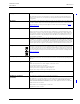


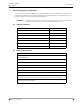

Table Of Contents
- Contents
- 1 Introduction
- 2 Practical Engineering Parameters
- 3 System LAN Cabling
- 4 System Power
- 5 Control Equipment
- 5.1 Preparation
- 5.2 Room Controller (NIRC3)
- 5.3 Preparing the Room Bus and Power Cables
- 5.4 Voice Piggy Back (NIVP)
- 5.5 Connection Terminals
- 5.6 Connecting the IP Room Controller Printed Circuit Board
- 5.7 LED Lamp Boards (NILD2)
- 5.8 Corridor Lamp (NICL2)
- 5.8.1 Installing the Corridor Lamp
- 5.8.2 Removing the Corridor Lamp Printed Circuit Board
- 5.8.3 Corridor Lamp Housing
- 5.8.4 NICL2 - Corridor Lamp Electrical Connections
- 5.8.5 4-Pole Connector Terminal
- 5.8.6 Connecting the Corridor Lamp Printed Circuit Board
- 5.8.7 LED Lamp Boards for the Corridor Lamp
- 5.8.8 Connecting the LED Lamp Boards
- 5.8.9 External Corridor Lamp Inputs
- 5.9 System Manager (NISM2)
- 6 Peripherals
- 6.1 Preparation
- 6.2 Installation Instructions
- 6.3 Backplates and Surface Mounting Spacer
- 6.4 Switch Module Electrical Connections
- 6.4.1 4-Pole Connector Terminal
- 6.4.2 Preparing the Wires for the 4-pole Connector Terminal
- 6.4.3 Connecting the wire in the 4-pole Connector Terminal
- 6.4.4 4-Pole Connector Terminal with Looped Wiring
- 6.4.5 Disconnecting a Wire from the Connector Terminal
- 6.4.6 Mounting the Switch Module to the Backplate
- 6.4.7 Mounting the Switch Module to the Surface Mounting Spacer
- 6.4.8 Dismantling the Switch Modules
- 6.4.9 Dismantling a Switch Module from a Spacer
- 6.4.10 Dip Switch Settings
- 6.5 Bedside Module (NIBM2)
- 6.6 Medical Rail Socket (NIMS2)
- 6.7 Door Side Module (NIDM)
- 6.8 Pull Cord Module - Active (NIPC-W3A)
- 6.9 Toilet Cancel Module - Active (NITC-XXA)
- 6.10 Pull Cord Module - Passive (NIPC-XXP)
- 6.11 Toilet Cancel Module - Passive (NITC-XXP)
- 6.12 Pull Cord Module (NIPC2) Active and Passive
- 6.12.1 Mounting the NIPC2 Pull Cord Module
- 6.12.2 Positioning the Back box for the Pull Cord Module
- 6.12.3 NIPC2 Back plate
- 6.12.4 Mounting the NIPC2 Backplate
- 6.12.5 Drilling the Backplate Mounting Holes
- 6.12.6 Mounting the Backplate on the Wall
- 6.12.7 Preparing the Cable for the Pull Cord Module
- 6.12.8 Room Bus Electrical Connections
- 6.12.9 Room Bus Address DIP Switch Settings
- 6.12.10 Passive Pull Cord Module Electrical Connections
- 6.12.11 Mounting the NIPC2 Pull Cord Module to the Backplate
- 6.12.12 Assembling and Attaching the Pull Cord
- 6.13 Duty Selector (NIDS)
- 6.14 Card Reader (NICR)
- 6.15 Speech Module (NISP)
- 6.16 Room Display (NIRD)
- 6.17 Television Interface Module
- 6.18 Sunblind Control Module
- 7 External Inputs
- 8 Wireless Functionality
- 8.1 General
- 8.2 Principle of the teleCARE IP with Wireless Functionality
- 8.3 teleCARE Wireless with Speech
- 8.4 teleCARE IP Wireless Planning
- 8.5 Wireless Infrastructure
- 8.6 Principle of the Wireless Infrastructure
- 8.7 teleCARE IP Wireless Components
- 8.7.1 NUREP Wireless Repeater
- 8.7.2 Outdoor Box
- 8.7.3 Wireless Gateway
- 8.7.4 NUWBM3 Wireless Active Bedside Module
- 8.7.5 NIRX teleCARE IP Transceiver
- 8.7.6 Connecting the Transceiver Module
- 8.7.7 NIVP Voice Piggyback Module
- 8.7.8 NIFX Fixed Transceiver
- 8.7.9 NITX Mobile Transceiver
- 8.7.10 NUUTX Universal Transceiver
- 8.7.11 NUWIR Wireless PIR Module
- 8.7.12 IR Range Test
- 8.7.13 NUUTX NUWIR Battery Placement
- 8.7.14 (3) Slide the battery lid back into place until it snap fits.NUUTX NUWIR Mounting Instructions
- 8.7.15 NILF Low Frequency Beacon
- 8.7.6 NILF Electrical Connections
- 8.7.7 NILF DIP Switch Settings
- 8.7.8 NILF Power Supply
- 9 Installation Examples
- 9.1 2-Bed Room with Active Toilet Cancel and Active Pull Cord Peripherals
- 9.2 2-Bed Room with Passive Toilet Cancel and Passive Pull Cord Peripherals
- 9.3 2-Bed Room with a Medical Rail Socket at each Bed
- 9.4 Room Controller with Corridor Lamps (Master/Slave)
- 9.5 4-Bed Room with Speech
- 9.6 Duty Selector at a staff Station
- 9.7 Positioning of the teleCARE IP Peripherals
- Document History

TD 93021US
17 July 2017 / Ver. PF3 4
Installation Guide
teleCARE IP
2 Practical Engineering Parameters
In order to ensure the optimal performance of a teleCARE IP system it is important to consider certain
parameters and limitations. The following tables show the most important practical values which can
have an influence on the teleCARE IP system performance.
WARNING: Any deviation from the values and recommendations shown in the following tables
can significantly reduce the performance of the teleCARE IP system.
2.1 General Limitations
2.2 Network Expectations
teleCARE IP Items
Practical Limits
NIRC3s per NISM Max. 200
Active peripherals per room bus (addressable - 0 to 3) Max. 4
Active peripherals per room bus (fixed address - 4 to 7) Max. 4
Pull cord peripherals on a passive bus Max. 1
Toilet cancel peripherals on a passive bus Max. 1
Total cable length of an NIRC3 IP room bus Max. 100 feet (30 meters)
Minimum IP room bus voltage 4.5 Vdc
Network Expectations
The LAN installation must be certified and tested in accordance with
ANSI/TIA/EIA-568-A.
The LAN must be dedicated and isolated from any general purpose LAN
The LAN installation should be in accordance with ANSI/TIA/EIA-568-A
LAN cable type: Category 5 (or higher)
Maximum LAN cable length: 328 ft (100 meters)
The LAN must only use switching equipment listed in UL file E360946.
A switch port is required for each room controller
Existing customer LANs must be assessed by Ascom before committing
(not applicable for UL2560 installations which prohibit use of customer LAN's)
For details of the teleCARE IP load and performance see document TD92636GB,
(IP Infrastructure Requirements)