
System Description

TD 93025US
9 May 2019 / Ver. I 5
System Description
teleCARE IP
2 Practical Engineering Parameters
In order to ensure the optimal performance of a teleCARE IP system it is important to consider certain
parameters and limitations. The following tables show the most important practical values which can
have an influence on the teleCARE IP system performance.
WARNING: Any deviation from the values and recommendations shown in the following tables
can significantly reduce the performance of the teleCARE IP system.
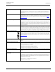
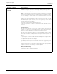
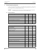
2.1 General Limitations
Practical engineering parameters (hardwired) Min. Max. Unit
NIRC3s per NISM 200 #
Active peripherals per room bus (addressable - 0 to 3) 4 #
Active peripherals per room bus (fixed address - 4 to 7) 4 #
Pull cord peripherals on a passive bus 1 #
Toilet cancel peripherals on a passive bus 1 #
Total cable length of an NIRC3 IP room bus 100/30 feet/meters
Minimum IP room bus voltage 4.5 VDC
Practical engineering parameters (wireless) Min. Max. Unit
Coverage planning
Number of NIRX's or gateways a wireless PD “should see”
(without RSSI locationing)
12#
Number of NIRX's or gateways a wireless PD “should see”
(with RSSI locationing)
23#
Range
NITX (indoor) 100/30 feet/meters
NIFX 100/30 feet/meters
NUWBM3 100/30 feet/meters
NUUTX 100/30 feet/meters
NUUTX input voltage 10 30 VDC
NUUTX distance to magnet from center 0.2/5 inch/mm
NUWIR 916 to 921 MHz 100/30 feet/meters
NUWIR PIR angle 20 90 degrees
NUWIR PIR range 13/4 20/6 feet/meters
NUREP 2.4GHz (indoor) 100/30 feet/meters