
System Description

TD 93025US
9 May 2019 / Ver. I 3
System Description
teleCARE IP
1.4 Integration With Other Ascom Systems
1.4.1 Ascom Communications Platform
The teleCARE IP system is part of the Ascom Communications Platform. By combining the various
Ascom communication systems a customer specific system solution can be provided which can include
speech, interactive messaging, local positioning, personal alarm and emergency call services. The
Ascom communication systems integrate through UNITE.
1.4.2 UNITE
The UNITE system integrates the ACP devices by offering an application level integration layer. UNITE
adds messaging, alarm handling, positioning, logging, fault handling, supervision, message routing,
group handling, number planning and other mission critical services.
UNITE allows the integration of third party equipment. Third party integration can be done via a
defined open access protocol on IMS or event detection via several configurable input alternatives on
XGate.
UNITE also allows third parties to develop their own customer-specific applications to be integrated
into the Ascom communications platform through Ascom open server solutions like Open Access
Server (OAS) for the MS Windows Common Object Model (COM) and the Open Java Server (OJS) for
the Java development platform.
System Enhancement
The features of a teleCARE IP system can be enhanced using the Unite Connectivity Manager (UNITE
CM) module. The UNITE CM module adds features like remote management, system supervision, error
logging, and message routing.
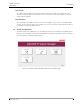
1.5 Typical Installation
1.5.1 Room Bus
A typical teleCARE IP installation consists of a teleCARE IP System Manager (NISM2 and later) and a
number of teleCARE IP Room Controllers (NIRC3 and later). Each room controller provides four 4-wire
digital room buses. Each room bus has 8 addresses for connecting up to 8 active peripherals such as:
corridor lamps, doorside modules, bedside modules, pull cord modules, toilet cancel modules and
medical rail modules.
One wire in the room bus is used for data, with a data rate of 2kbps. Another wire is reserved for
speech communication, and one pair of wires is used for the required power supply from the room
controller to the peripheral modules. The peripheral modules on the room bus are constantly
monitored and all outputs are short circuit protected.
1.5.2 Passive Bus
Several teleCARE IP active peripherals are equipped with a passive bus connector for the connection of
additional passive peripherals. See “Passive Peripherals” on page 24. for an overview of all the
interconnections that can be made between active and passive peripherals.
1.5.3 Power Supply
The system power supply requirement is 24Vdc distributed on a 24Vdc two-wire power supply
network. The cable size, cable length and system load will influence the effective voltage around the
system. Therefore the power supply capacity, cable types and wire size must be calculated for each
installation.