PRESSURE GAUGE INSTALLATION, OPERATION AND MAINTENANCE I&M008-10098-5/02 (250-1353-K) Rev.
CONTENTS Page Selection and Application Range . . . . . . . . . . . . . . . . . . . . . . . . . . . . . . . . . . . . . . . . . . . . . . . . . . . . . . . . . . . . . .4 1.1 1.2 Temperature . . . . . . . . . . . . . . . . . . . . . . . . . . . . . . . . . . . . . . . . . . . . . . . . . . . . . . . . . .4 1.3 Media . . . . . . . . . . . . . . . . . . . . . . . . . . . . . . . . . . . . . . . . . . . . . . . . . . . . . . . . . . . . . . .4 1.4 Oxidizing media . . . . . . . . . . . . . . . . . . . . . . . .
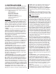
Glycerin satisfies most applications. While being the least expensive fill, its usable temperature range is 20/180°F. Silicone filled gauges have a broader service range: –40/250°F. Oxidizing media require the use of Halocarbon, with a service range of –40/250°F. Pointer motion will be slowed at the low end of the low end of these temperature ranges. 1.7 Mounting – Users should predetermine how the gauge will be mounted in service: stem (pipe), wall (surface) or panel (flush).
750°F (400°C) the customers should use their own small diameter piping to avoid possible corrosion of the stainless steel. The five foot capillary will protect the gauges used on the common cryogenic (less than –300°F (200°C) gases, liquid argon, nitrogen, and oxygen.) The capillary and gauge must be cleaned for oxygen service. The media must not be corrosive to stainless steel, and must not plug the small bore of the capillary. 2.
f. Method – ASME B40.100 recommends that known pressure (based on the reading from the pressure standard used) be applied to the gauge under test. Readings including any error from the nominal input pressure, are then taken from the gauge under test. The practice of aligning the pointer of the gauge under test with a dial graduation and then reading the error from the master gauge (“reverse reading”) can result in inconsistent and misleading data and should NOT be used.
dropped or overpressured and the Bourdon tube takes a permanent set. This error may often be corrected by simply repositioning the pointer. Except for test gauges, it is recommended that the pointer be set at midscale pressure to “split” the errors. Span – A span error exists when the error at full scale pressure is different from the error at zero pressure. This error is often proportional to the applied pressure.
of the gauge. If the friction error is excessive, the movement should be replaced. One possible cause of excessive friction is improper adjustment of the hairspring. The hairspring torque,or tension, must be adequate without being excessive. The hairspring should also be level, unwind evenly (no turns rubbing) and it should never tangle. NOTES: 1 For operation of test gauge external zero reset, refer to page 17. 2 For test gauge calibration procedure, refer to Figure 2 on page 18.
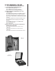
.0 TEST EQUIPMENT & TOOL KITS See our website www.ashcroft.com for more details 9.1 Pressure Instrument Testing Equipment Type 1305D Deadweight Tester Type 1327D Pressure Gauge Comparator Type 1327CM “Precision” Gauge Comparator 9.
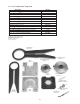
9.4 21⁄2 & 31⁄2 1009 Duralife® Gauge Tools Part No.
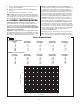
ASHCROFT® Type 1188 Bellows Gauge Calibration Procedure CALIBRATION & TROUBLE CORRECTION DIAGRAM RANGE SPAN ADJUSTMENT RANGE TOO SHORT Adjust slide “S” inward POINTER JUMPING STICKY PARTS Clean all bearings and gear teeth RANGE TOO LONG Adjust slide “S” outward NOTE: After adjusting range span, set both movement stops. Set the underload stop so that the pointer will stop at zero. Set the overload stop so that the pointer will pass the maximum range approximately 5˝.
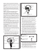
ASHCROFT® Previous Type 1009 Duralife® Calibration Procedure – Vacuum Range 1. Remove ring, window and gasket pointer. 15. recheck accuracy at 15 and 25˝ Hg vac. (Figure 2). 2. Using a pencil, refer to dial and mark the 0 and 25˝ Hg positions on the case flange. 16. Reassemble window, gasket and ring. 3. Remove dial. Figure 2 – 4. Apply 25˝ Hg vac. 5. Lightly press pointer onto pinion carefully aligning it with the 25˝ Hg vac. mark on the flange. 15 6. Release vacuum fully. 7.
ASHCROFT® Previous Type 1009 Duralife® Calibration Procedure – Pressure Range Step 1. With the dial off, install pointer at 9 o’clock “lightly,” Figure 3. Step 5. Install pointer centered in zero box, Figure 4. Step 6. Go to full scale pressure…check that pointer is within 1% of full scale mark. If not, remove pointer and dial and return to step 1, Figure 4. Figure 3 – Start Point Step 7. Go to mid-scale pressure…rotate dial until midscale mark is aligned with pointer, Figure 4. Step 8.
ASHCROFT® Current Type 1009 Duralife® Calibration Procedure – Pressure and Vacuum Range Calibration – 1009 Duralife® Gauge – Inspect gauge for accuracy. At times gauges are simply “off zero” and opening the ventable plug at the top of the gauge will relieve internal gauge pressure and correct the offset.
Type 1279 & 1379 Solid Front Duragauge® Pressure Gauge Liquid Fill Conversion Instructions TYPICAL 45-1279_S-04L-100* GAUGE SHOWN WITH KIT 101A202-01 “O” Ring Acrylic Window Elastomeric Diaphragm with Integral “O” Ring Threaded Ring 1279 Rear Cover 1379 41⁄2˝ LOWER 41⁄2˝ BACK 41⁄2˝ LOWER 41⁄2˝ BACK 6˝ LOWER & BACK KIT PART NO.
Type 1279 & 1379 Solid Front Duragauge® Pressure Gauge Liquid Fill Conversion Instructions INSTRUCTIONS FOR USING CONE TOOL AND RING WRENCH BACK CONNECTION ASSEMBLED GAUGE Fig. 2 REAR COVER Garter Spring & Diaphragm Assembly (Back Connection Gauge Only) DIAPHRAGM A. Place cone tool over socket shank as shown. B. Moisten lip of socket and outer O-ring surface with silicone oil or grease. C. Place diaphragm with rib side facing upward over cone into case grove.
ASHCROFT® Type 1082 Test Gauge Calibration Procedure – Pressure Range I NSTRUCTI ONS FOR USE OF EXTERNAL EASY ZERO™ ADJUST FEATURE* Fi g. 1 A B RING 1. LOOSEN RING-LOCKING SCREW A. 2. OBTAIN REQUIRED ADJUSTMENT BY ROTATING KNOB B CLOCKWISE OR COUNTER-CLOCKWISE. 3. TIGHTEN SCREW A DOWN ON KNOB B. *Applicable only for test gauge with hinged ring design. ADDI TI ONAL CALI BRATI ON I NSTRUCTI ONS 1) “Standards shall have nominal errors no greater than 1 ⁄4 of these permitted for the gauge being tested.
Installation and Maintenance Instructions for ASHCROFT® Type 1082 Test Gauge Calibration Procedure – Pressure Range THIS TEST GAUGE IS PROVIDED WITH A MICROSPAN™ ADJUSTMENT TO SIMPLIFY CALIBRATION. THE FLOW CHART BELOW OUTLINES THE RECOMMENDED CALIBRATION PROCEDURE Fi g. 2 CENTER DIAL OVER PINION SET POINTER AT 0% GO TO 100% >0.2 <1.5% MICROMETER SPAN CHECK ACCURACY >1.5% COARSE SPAN <0.2% MICRO SPAN COARSE SPAN SET POINTER AT 100% SET POINTER AT 100% GO TO 0% GO TO 0% MICRO SPAN >0.
Ashcroft Inc., 250 East Main Street Stratford, CT 06614-5145 U.S.A. Tel: 203-378-8281 Fax: 203-385-0408 (Domestic) Fax: 203-385-0357 (International) email: info@ashcroft.com www.ashcroft.com I&M008-10098-5/02 (250-1353-K) Rev. 01/12 Visit our web site www.ashcroft.