
Owner's manual
MODEL CXLdp DIFFERENTIAL
PRESSURE TRANSDUCER
INSTALLATION & MAINTENANCE SHEET
Follow the terminal block label markings on the
CXLdp to identify the terminals;
• 4-20mA Ouput: The left, negative (-), and
right, positive (+) terminals are used, ignore
t
he center terminal which is not used. Con-
nect the power supply positive lead to the
Reverse Wiring Protected
Electrical Connection: unpluggable terminal block
accepts 12-26 AWG
Operating Temperature: 0-160°F
Enclosure:
NEMA 1 Fire-retardant ABS Meets UL 94-5VA
Weight: Approx. 2.5 oz.
Pressure Connection Options:
1
⁄4˝ Brass Barbs or
1
⁄8 NPT Female Brass
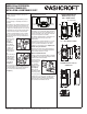
Optional:
1
⁄2˝ conduit
or plenum mount-
ing bracket and
cover available as
separately ordered
kit – part number
101A213-01.
(see Figure 2)
INSTALLATION
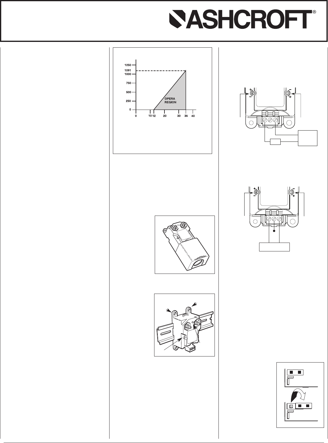
Mounting:
The transmitter
can be mounted
on a 35 mm DIN
rail or with #8 or
#10 screws using
the 4 mounting
holes provided.
Torque limits on
the mounting
holes provided is
6 inch-pounds.
(see Figure 3)
Electrical Wiring:
1. The use of sheilded cable is recommended for
optimum performance. Connect the shield to the
guard terminal on the reading instrument (meter,
etc.) if available or to ground.
2. Remove the terminal block on the front of the
transmitter.
3. Available electrical versions are:
a.) CURRENT 4-20mA; black terminal block.
b.) VOLTAGE 0-5Vdc/0-10Vdc; green terminal
block.
© 2011 Ashcroft Inc. 250 East Main Street 06614, Tel: 203-378-8281 • Fax: 203-378-0499, All specifications are subject to change without notice.
All sales subject to standard terms and conditions. www.ashcroft.com All rights reserved. I&M011-10130 Rev. A 10/12
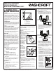
V
min
= 12V+ [.022A*(R
L
)]
*includes a 10% safety factor
R
L
=R
S
+ R
W
R
L
= Loop Resistance (ohms)
R
S
= Sense Resistance (ohms)
R
W
= Wire Resistance (ohms)
Figure 1 Load Limitations 4-20mA Output
TING
Loop Resistance (Ω)
Loop Supply Voltage (Vdc)
*
F.S. pressure is equivalnt to the span of the transmitter (16mA).
Figure 3
Green LED
Use
#10
screw
Use #8
screw
or
Zero Pot
Figure 2
WARNING! READ
BEFORE INSTALLATION
1. GENERAL:
A failure resulting in injury or damage may be
caused by excessive overpressure, excessive
vibration or pressure pulsation, excessive
instrument temperature, corrosion of the pres-
sure containing parts, or other misuse. Con-
sult Ashcroft Inc., Stratford, Connecticut, USA
before installing if there are any questions or
c
oncerns.
2. OVERPRESSURE:
Pressure spikes in excess of the rated overpres-
sure capability of the transducer may cause irre-
versible electrical and/or mechanical damage to
the pressure measuring and containing ele-
ments.
3. STATIC ELECTRICAL CHARGES:
Any electrical device may be susceptible to dam-
age when exposed to static electrical charges.
To avoid damage to the transducer the
operator/installer should follow proper ESD
(electrostatic discharge) protection procedures
before handling the pressure transducer.
DESCRIPTION
The Ashcroft
®
Model CXLdp is a low differential
pressure transmitter to be used on clean, dry,
non-corrosive gases. It is available in two accuracy
classes and its performance is traceable to the
U. S. National Institute of Standards and Technol-
ogy (NIST). The 8 or 4 located in the third position
of the product code distinguishes a 0.8% from a
0.4% accuracy transmitter. Both unidirectional
(e.g. 0 to +1.0 IW) or bi-directional (e.g. ±2.0 IW)
models are available. A green LED located on the
front of the transmitter indicates power and opera-
tional status. The LED light intensity increases as
pressure increases.
SPECIFICATIONS
Accuracy: (2) options,specified at time of order.
• ±0.8% span
- (±0.128mA for 4-20mA output units)
- (±0.08V for 0-10Vdc output units)
or
• ±0.4% Span
- (±0.064mA for 4-20mA units)
- (±0.04V for 0-10Vdc output units)
Output Signal: Specified at time of order.
• 4-20ma (For symmetric bidirectional ranges
0IW= 12mA
or
• 0-10Vdc; 0-5Vdc User selectable option (For
symmetric bidirectional ranges 0IW= 5 or
2.5Vdc respectively).
Supply Voltage:
• 4-20mA: 12-36 Vdc (no regulation required)
(see Figure 1)
or
• 0-10Vdc (0-5Vdc User selectable option):
14-36 Vdc or 24 Vac (+/- 20%)
• Supply Current: 6mA (4.5mA for 5Vdc
output option)
– +
+
––
+
P
OWER
SUPPLY
BCS
SPAN
ZERO
CXLdp positive terminal, connect the negative
power supply lead to the negative terminal of
the BCS 4-20mA input. Last, connect the (-)
negative terminal on the CXLdp to the (+)
positive BCS input.
Z
ero adjust
p
otentiometer
S
pan adjust
potentiometer
• 0-10Vdc; 0-5Vdc Output: Follow label mark-
ings for terminal assignments; COM is for
Common (supply and output negative), V
IN
is for supply positive and VOUT is for output
signal. The CXLdp Voltage Output unit is sup-
plied as standard with 0-10 V output, to con-
vert to 0-5 V output see following
instructions.
- 0-10 Vdc Output: Product is supplied as
standard with 0-10 V output, see instruction
below to access the Voltage Output jumper.
- 0-5 Vdc Output: See below for proper
jumper selection. To convert the unit from a
0-10 V output to a 0-5 V output unit note the
following. Access the jumper by simultane-
ously pushing both housing tabs away from
the housing, see drawings under “General
Dimensions” for
details. Change
jumper (orange)
into position as
shown below,
carefully reattach
housing cover.
When finished
mark check box
on front label in-
dicating that the
unit now provides
a 0 – 5Vdc output.
0-10 Vdc
0-5 Vdc
Label Part No. 238A713-01
Figure 4
Jumper
(orange)
SPAN
ZERO
+
–
POWER SUPPLY
V
Out
Vin (V+, Supply)
Common (V
–)
Z
ero adjust
potentiometer
Span adjust
potentiometer