
Instruction Manual

Installation and Maintenance Instructions for
ASHCROFT
®
G-Series Snap Action Switches
for Low Range Differential Pressure Control
OPERATION
The ASHCROFT
®
differential pressure control is a precision
device which features a snap action switch. Fixed deadband is
available with single or dual SPDT independently adjustable
switches with various electrical ratings. Adjustable deadband is
available with a SPDT switch with various electrical ratings.
Several wetted material constructions for compatibility with
pressure media may be obtained.
Series GD-S switches have a fixed deadband which will be
within the limits noted on the nameplate.
Series GD-D switches may be set to operate simultaneously
or up to 85 percent of the range apart. The deadband of each
switch will be within the limits noted on the nameplate.
Series GD-A switches may be set to operate with any dead-
band within the limits sho
wn on the nameplate.
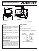
MOUNTING
The “G”
Ser
ies ASHCROFT
®
snap action differential pressure
switch has a NEMA-4X enclosure made of 316 stainless steel.
Two holes in the bracket supplied are used to surface mount
the control. Location of these holes is shown on the general
dimension drawings. An optional pipe mounting bracket is also
available. Mount on a vibration free surface or pipe in any
or
ientation.
PRESSURE CONNECTIONS
F
or oper
ation as a pressure control, connect the pressure source
to the lower port marked “H.” If venting is required, connect vent
line to side port marked “L.” If no venting is required, port “L”
must be left open.
For operation as a differential control – connect the high pres-
sure to the lower port marked “H” and the low pressure to the
side por
t mar
ked “L.”
When tightening control to pressure lines, always use the
wrench flats or hex on the pressure connection.
NEVER
TIGHTEN BY
TWISTING
THE CASE
.
CONDUIT CONNECTIONS
One
3
⁄
4 NPSM conduit adapter of 316 stainless steel is provided.
It is recommended that Teflon tape or other sealant be used on
conduit bushing or plug threads to ensure integrity of the
enclosure.
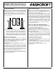
ELECTRICAL CONNECTION
Remove cover, held in place by four screws.
On all units except one with terminal blocks – wire directly to
the switch according to circuit requirements. Units with terminal
blocks – wire directly to terminal blocks as required. Terminals
are mar
ked common (C), normally open (NO) and normally
closed (NC).
STA
NDARD RANGES
3
0, 60, 100, 150 in.H
2
O
Differential
3.9 lbs. (1.8kg)
1 2 3
1 2 3
LEFT SWITCH
TERMINAL BLOCK
RIGHT SWITCH
TERMINAL BLOCK
SERVICE LEADS TO THESE TERMINALS
NC
NO
C
2.64
(67)
4
.78
(
121)
3.50
(89)
Ø 5 . 1 2
( 13 0 )
1. 7 5
( 44 )
5
.6 8
(
1 4 4 )
1 .6 0
( 41 )
2 . 1 0
(5 3 )
1 .8 6
( 47 )
0 .38
( 10 )
4. 17
(1 0 6)
4
.89
( 12 4)
3 . 4 8
( 8 8 )
3/4 NPT FEMALE
CONDUIT ADAPTER
1 /4 NPT FEMALE
HIGH PRESSURE PORT
1 /4 NPT FEMALE
LOW PRESSURE PORT
© 2007 Ashcroft Inc., 250 East Main Street, Stratford, CT 06614-5145, USA, Tel: 203-378-8281, Fax: 203-385-0499, www.ashcroft.com
All sales subject to standard ter
ms and conditions of sale
.
I&M009-10021-10/00 (250-2893) AMR 12/07