
Manual
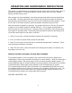

OPERATORS AND MAINTENANCE INSTRUCTIONS
This scraper is a durable piece of equipment and with proper care will yield many years of
trouble free operation. The scraper requires a power source with one 4-way (double
acting) hydraulic control valve.
After scraper has been assembled, it should be greased at all points where grease fittings
are provided. Connect hydraulic hoses to tractor and operate the scraper to maximum
raise and drop several times to force any air from the hydraulic lines and cylinders. Check
the oil level in the tractor hydraulic system and add to maintain the proper level.
When the scraper is placed into operation, the operator will have to ”feel out” the amount
of depth of cut to obtain maximum loading efficiency. This is usually accomplished by
taking a lesser and more uniform cut. However, some soil conditions such as loose sand
may require a “pumping action” obtained by taking successive deep cuts and lifting out of
cut as the tractor begins to lose power or traction.
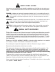
1. After 10 hours work, all bolts should be checked and tightened if necessary.
2. Every 10 hours all grease fittings should be lubricated.
3. After 50 hours work, all bolts should be rechecked and tightened if necessary. Check
wheel bearings and adjust if necessary.
4. After 300 hours work, clean and repack wheel bearings and replace, if necessary, cut-
ting edges, worn pins, etc.
SPREAD CONTROL ON MODEL 450 AND 500 SCRAPERS
The hydraulic cylinder on the rear section of the main frame controls the distance the
cutting edge is from the ground after the bucket is in dump position. When the bucket first
reaches dump position, the cutting edge is at the minimum spreading depth (approx. 2”)
and as additional depth of spread is desired, the same hydraulic control valve on the tractor
is actuated and the cutting edge raises allowing for the increased depth of spread.
This is accomplished when the flow of hydraulic oil is automatically diverted from one of
the hydraulic cylinders on the side of the scraper to the hydraulic cylinder at the rear. The
rear cylinder lifts the entire main frame and bucket assembly upward, allowing for the
increased distance between the cutting edge and the ground.
ASHLAND INDUSTRIES, INC.
3