
Manual
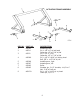
MODELS 450 & 500 SCRAPER ASSEMBLY INSTRUCTIONS
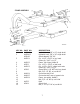
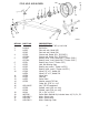
1. A suitable hoist or lift should be available for assembly.
2. Pack wheel bearing with grease and install hubs to rear spindles and front axle assembly. Be
sure to follow the bearing numbers as shown in the parts listing as the front hubs require different
bearings than the rear.
3. Raise actuating frame over bucket and lower into place so that the holes in the arms of the
actuating frame aligns with the rear hole on each side of the bucket. Insert 1 ¼ ” x 2-9/16” pin
(with tab type head) from the inside of the bucket. Secure with 5/8” x 1 ½ ” NF bolt through
bucket side with locking nut to the outside.
4. Connect actuating arm bars to the front holes in the bucket. In doing so, be sure that the cast
roller on the opposite end of the actuating arm is in the up position and facing inward. Insert 1 ¼
x 2-9/16 ” pin (with tab type head) from the inside on the bucket. Secure with 5/8” x 1 ½ ” NF
bolt through the bucket side with lockwasher and nut to the outside.
5. Connect a short chain from the cutting edge to the cross pipe of the actuating frame, then
raise this bucket and actuating assembly over the main frame and lower into place so that the
front of the actuating frame can be connected to the 1 ½ ” ID bearing on the side of the main
frame. Secure with 1 ½ ” x 5-5/8” pins on each side. Lock these pins in place by turning the pin
until the hole in the head aligns with threaded hole in the actuating frame, then secure with ½” x 1”
NC capscrew and lockwasher.
6. Lift front end of actuating arms and connect to the brackets on the front frame cross member
using the 1 ¼ ” x 4-1/8” pins. Secure with ¼” x 2” cotter pin.
7. Raise the apron assembly over the scraper and lower into position so that the holes in the arms
of the apron align with the holes in the bucket sides. Insert the 1 ¼ ” to 1” shoulder pin through
the apron arms and into the bucket. Install lock nut inside the bucket and tighten securely.
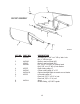
8. Installing the hydraulic cylinders:
A. Install the cylinder with three hose ports on the left side of the scraper with the rod end to
the actuating frame and the grease hole in the rod end bushing facing up. Use 1-1/8” x 3 ¼”
pin at the base of the cylinder. Secure with 3/16” x 1 ½” cotter pins. Use 1-1/8” x 6” pin at
the rod end of the cylinder. Secure with ½” x 1” NC capscrew and lockwasher.
B. Install 3/8” NPT 90° swivel adapter in all three ports of the cylinder. Tighten so that the
swivel will be facing toward the rear. The extreme forward swivel will have to be turned slightly
to the outside so that the hose will clear the swivel in the center port.
C. Connect a 3/8” x 18” hose from the forward pipe line on the frame cross-member to the
base (rear) port of the cylinder.
D. Connect a 3/8” x 36” hose from the pipe line on the frame cross-member tot he center
port of the cylinder.-
E. Connect a 3/8” x 36” hose from the center pipe line on the frame cross-member to the
extreme forward port of the cylinder.
5