Film-Tech The information contained in this Adobe Acrobat pdf file is provided at your own risk and good judgment. These manuals are designed to facilitate the exchange of information related to cinema projection and film handling, with no warranties nor obligations from the authors, for qualified field service engineers. If you are not a qualified technician, please make no adjuatments to anything you may read about in these Adobe manual downloads www.film-tech.
ASHLY POWERCARD AMPLIFIER INPUT OPTIONS ITC-2, CL-2, XR-1, MM-6 TABLE OF CONTENTS Installation ....................................................................... 2 ITC-2 Input Transformer ................................................. 3 CL-2 Limiter .................................................................... 4 XR-1 Crossover ............................................................... 6 MM-6 Mixer .................................................................... 9 Specifications ....
shipping. In the event that damage has occurred, immediately notify your dealer so that a written claim to cover the damages can be initiated. The right to any claim against a public carrier can be forfeited if the carrier is not notified promptly and if the shipping carton and packing materials are not available for inspection by the carrier. Save all packing materials until the claim has been settled. ITC-2 INPUT TRANSFORMER ............................................
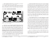
without saturating the transformer core. (Core saturation is the magnetic equivalent of clipping, and results in a distorted signal) To install a transformer in the standard input, cut and remove the two jumpers (solid color with one black stripe) for each transformer, as indicated in figure 2. These jumpers are referenced on the circuit board as well. Insert the transformer assembly into the five pin socket and fasten with the provided screws. CL-2 DUAL COMPRESSOR/LIMITER ..............................
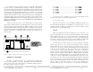
Figure 4: CL-2 connector locations applications. While our rack-mount crossovers use state-variable filters for flexibility, the nature of this product suggests using two fixed-frequency cascaded butterworth response filters for each output. The low output includes an 18dB/oct. 20Hz hipass filter to reduce subsonic signal. The high output includes 360° of phase control for driver alignment as well as two types of CD horn EQ.
In a biamped system, low frequency audio power typically outweighs high frequency power by a significant margin, depending on efficiency of the speakers. For example, a biamped system might require 300 watts for the low end but only 100 watts or less for the high frequency drivers. This is because high frequencies convert to acoustic energy much more efficiently than lows.
The simplest solution is to physically align the voice coils, but when this is impractical the XR-1 allows you to adjust the phase of the high frequency output. To do nothing to the phase, leave the control at 0. To achieve best results when aligning drivers, we encourage you to use appropriate audio measurement tools when configuring the system. CD HORN EQ CD horn EQ is simply a 6dB/oct. high frequency shelving filter to compensate constant directivity horn designs for flat, on axis response.
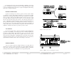
the signal both in and out of the mixer/amplifier combination. The insert points are interrupting, meaning the insertion of a plug will interrupt the signal going to the amplifier. The tip is the return, or input to the amplifier, while the ring is the send, or output of the mixer.
CL-2: Limiter Option SPECIFICATIONS ITC-2: Input Transformer Option Input Type . . . . . . . . . . . . . . . . . . Transformer balanced Input Impedance . . . . . . . . . . . . . . >20KΩ Max Input to transformer . . . . . . . +7 dBu (transformers follow input attenuators) Insertion Loss . . . . . . . . . . . . . . . . 0 dB ±0.3dB at 1KHz Frequency Response . . . . . . . . . . ±0.3dB 20Hz-20KHz THD . . . . . . . . . . . . . . . . . . . . . . . .007% at 1KHz and +7 dBu .