
Specifications


Ashly POWERCARD Owners Manual Ashly POWERCARD Owners Manual
Page Page2
shipping. In the event that damage has occurred, immediately notify your
dealer so that a written claim to cover the damages can be initiated.
The right to any claim against a public carrier can be forfeited if the carrier
is not notified promptly and if the shipping carton and packing materials are not
available for inspection by the carrier. Save all packing materials until the claim
has been settled.
INSTALLATION......................................................................
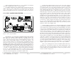
Figure 1: Input option removal and assembly
Before installing an input option, be sure to disconnect the amplifier from
power. To remove the standard input panel, unscrew the four corner screws and
gently pull the assembly out. There will be two terminals already connected and one
remaining disconnected. The two 3-conductor shielded wires which terminate at the
six pin header are the audio signal paths to the amplifier. Slowly rock the connector
back and forth while exerting a constant pull and it will come right off. Note that there
is a friction lock tab and ramp on the header set, indicating proper polarity during
reassembly. The black wire terminated with a spade fast-on is the chassis ground.
This is connected to the PCB via a riveted fast-tab. If during reassembly this fast-on
feels loose, remove and squeeze the blue spade with pliers to assure good contact. The
last connector, the power supply, is shipped disconnected because the standard input
is passive. Depending on the amp model, these three wires will be either red, violet,
and black, or blue, blue, and yellow. The three pin power supply header set is
polarized for proper mating. Once these three connectors are plugged into the new
option, gently replace the panel and screws.
3
ITC-2 INPUT TRANSFORMER ............................................
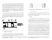
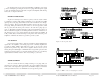
Figure 2: Input transformer assembly diagram
The transformer input option may be installed in either channels 1 or 2 or
both. The input transformer provides complete electrical isolation between the
amplifier and its signal source to eliminate any ground-induced hum noise. The
transformer input also further reduces any common-mode noise and radio
frequency interference. The precision 1:1 transformer will not affect any controls
on the standard input. Input attenuation occurs prior to the primary windings,
allowing for high level input signals
Power Suppl y Connect or
(Location may vary)
Signal Connector
(Observe Polarity)
Ground Connector
(Location may vary)
1.) Channel one optional transformer socket.
2.) Cut and remove these two jumpers before inserting channel one transformer.
3.) Signal header connector
4.) Channel two optional transformer socket.
5.) Cut and remove these two jumpers before installing channel two transformer
6.) Ground connector
#
"
!
$