
Specifications


Ashly POWERCARD Owners Manual Ashly POWERCARD Owners Manual
Page Page10
The simplest solution is to physically align the voice coils, but when this is
impractical the XR-1 allows you to adjust the phase of the high frequency output.
To do nothing to the phase, leave the control at 0. To achieve best results when
aligning drivers, we encourage you to use appropriate audio measurement tools
when configuring the system.
CD HORN EQ
CD horn EQ is simply a 6dB/oct. high frequency shelving filter to compen-
sate constant directivity horn designs for flat, on axis response. The XR-1 allows
you to switch frequencies depending on the horn size your application requires.
Use the low frequency for larger, lower frequency horns, and use the high
frequency for smaller, higher frequency horns.
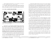
MM-6 MIC/LINE MIXER ......................................................
Figure 7: MM-6 mic/line mixer
The MM-6 is a practical solution to one of the most fundamental needs in
audio . . . control the volume of several voice and program signals and amplify
them to a loudspeaker. Combined with any of our PowerCard compatible
amplifiers, this handy tool eliminates the need for outboard mixers in many
applications. You can run two microphone inputs and up to four line level inputs,
each with a discrete level control. The two microphone inputs have a switchable
200Hz low-cut filter to reduce wind, floor, or breath noise. Insert points are
available for interfacing with external
11
devices, such as equalizers. +15 Volt phantom power is available for use
with most condenser mics by switching an internal jumper (no soldering
required). See figure 9 for location of the phantom power switch. An LED
indicates the on/off status of phantom power.
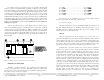
MIC INPUTS
The microphone inputs are balanced, with an initial gain of 20dB, and a
maximum input level of 0dBu. Any signal above this level will clip the input
stage and become distorted. The mic level controls add up to an additional 15.6dB
of gain to the mic signal. The master level control then adds up to an another
15.5dB to the signal, at which point the signal is sent off to the amplifier. Since
there are no clipping indicators on this product, a little common sense and
attention to gain stage detail will prevent unnecessary clipping. Each mic input
is routed to both amplifier channels. It is not possible to select one mic to one
channel and the other mic to a different channel.
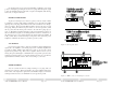
LINE INPUTS
The line level controls passively attenuate the signal prior to its reaching
the summing bus. This means that the line level inputs are not limited by a
maximum input level. If the amplifier is well within it's power range and yet the
sound is distorted, chances are that somewhere in the MM-6 the signal is too hot.
A good starting point, for both line and mic inputs, is to set the master level at
5 and then increase the level controls until the desired volume is reached.
If the amplifier is configured in stereo mode, line input channels one and
three are routed to amplifier channel 1, while channels two and four correspond
to amplifier channel 2. When in mono/normal or bridged/mono mode, the stereo
signals are summed together, effectively giving you four mono line inputs as well
as the two mic inputs.
INSERT POINTS
Insert points are available for each output channel of the mix. Should you
wish to use an external processing device such as an equalizer, compressor, noise
gate, tape deck, or even another amplifier, the insert points allow you full access
to