MFA-8000 MFA-6000 Power Amplifier Operating Manual ASHLY AUDIO INC. 847 Holt Road Webster, NY 14580-9103 Phone: (716) 872-0010 Toll-Free: (800) 828-6308 Fax: (716) 872-0739 Internet: http://www.ashly.
Operating Manual - MFA-8000 and MFA-6000 Power Amplifier Table Of Contents 2 1 INTRODUCTION . . . . . . . . . . . . . . . . . . . . . . . . . . . . . . . . . . . . . . . . . . . . . . . . . 4 2 UNPACKING . . . . . . . . . . . . . . . . . . . . . . . . . . . . . . . . . . . . . . . . . . . . . . . . . . . . . . 4 3 AC POWER REQUIREMENTS . . . . . . . . . . . . . . . . . . . . . . . . . . . . . . . . . . . . . . 3.1 AC Voltage Requirements. . . . . . . . . . . . . . . . . . . . . . . . . . . . . . . .
Operating Manual - MFA-8000 and MFA-6000 Power Amplifier 9 TYPICAL APPLICATIONS . . . . . . . . . . . . . . . . . . . . . . . . . . . . . . . . . . . . . . . . 9.1 Stereo Operation . . . . . . . . . . . . . . . . . . . . . . . . . . . . . . . . . . . . . . . . . . . . . . . . 9.2 Parallel Mono Operation . . . . . . . . . . . . . . . . . . . . . . . . . . . . . . . . . . . . . . . . . 9.3 Bridged Mono Operation . . . . . . . . . . . . . . . . . . . . . . . . . . . . . . . . . . . . . . . . .
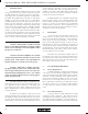
Operating Manual - MFA-8000 and MFA-6000 Power Amplifier 1. INTRODUCTION The MFA Series amplifiers achieve the very high energy levels used in today’s professional sound systems, carefully maintaining control and accuracy while delivering high power to modern loudspeaker configurations. The MFA 8000 (MFA 6000) will deliver 1200 Watts (800W) per channel into 4Ω, and up to 3000 Watts (1800W) bridged-mono into 4Ω.
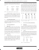
Operating Manual - MFA-8000 and MFA-6000 Power Amplifier peaking at the clipping level, the following AC line current capacities are recommended for system design purposes: Load MFA-6000 MFA-8000 Idle 8Ω × 2 4Ω × 2 2Ω × 2 1 Amp 7.5 Amps 10 Amps 15 Amps 1.2 Amps 10 Amps 15 Amps 20 Amps Table 3.1: Recommended AC line current capacity Both MFA amplifiers consume less than 12 amps when operating at 1/8 power into 2Ω loads.
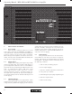
Operating Manual - MFA-8000 and MFA-6000 Power Amplifier 6. FRONT PANEL FEATURES 6.1 Power Switch When the unit is switched on there is a 2 second delay, during which time the PROTECT and LIMIT circuits will activate. The load is disconnected during this power-up sequence, and the input signal is attenuated. When turning off the amplifier, the load is removed instantly, and the protect and limit LEDs will briefly turn on as the power supply discharges. 6.
Operating Manual - MFA-8000 and MFA-6000 Power Amplifier 6.5 Thermal Indicator This yellow LED indicates that the internal temperature of the amplifier is too high in one or more places. Intensity of the LED is proportional to temperature above normal. Note that if the thermal LED occasionally comes on dimly, this is not considered excessive.
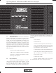
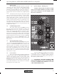
Operating Manual - MFA-8000 and MFA-6000 Power Amplifier Figure 7: Input Section 7. REAR PANEL FEATURES 7.1 Inputs The standard input panel of the MFA series amps is equipped with balanced 1/4" tip-ring-sleeve (TRS) phone jacks, balanced XLR jacks, and balanced screwterminal inputs. The three types of connectors are internally wired in parallel and may be used with balanced or unbalanced connections.
Operating Manual - MFA-8000 and MFA-6000 Power Amplifier Input Ground The CHASSIS GROUND terminal is internally connected to the chassis, the AC earth ground, and the power amplifier’s signal ground. The INPUT GROUND terminal is tied to the XLR pin 1 and the 1/4" jack sleeve. It is recommended that the input and chassis ground terminals remain connected with the factory-supplied jumper strap.
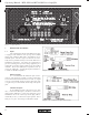
Operating Manual - MFA-8000 and MFA-6000 Power Amplifier 7.6 Speaker Outputs - Speakon Connectors Neutrik Speakon connectors are provided to connect with the Neutrik NL4FC 4-conductor plug. For the channel 1 and 2 Speakon connectors, the following pin assignment is used: Pin 1+ = speaker hot 8.2 Peak Limiter/Compressor The limiter input option provides peak signal limiting from excessive input levels for speaker protection and overall level control.
Operating Manual - MFA-8000 and MFA-6000 Power Amplifier Figure 8.2: CL-2 Peak Limiter Compressor Figure 8.3: XR-1 Two-Way Crossover Figure 8.
Operating Manual - MFA-8000 and MFA-6000 Power Amplifier 9. TYPICAL APPLICATIONS 9.1 Stereo Operation (Both switches out, both inputs used, both level controls used, both outputs used) 9.
Operating Manual - MFA-8000 and MFA-6000 Power Amplifier 9.3 Bridged Mono Operation (Normal/bridging switch in, channel 1 input used, channel 1 level control used, BRIDGED output used) 10. DESIGN THEORY The MFA Series amplifiers are based on a dualmonaural design with each channel being electrically and physically identical. This type of design improves audio performance by eliminating power supply interaction and crosstalk. Failure of one channel will not affect the other.
Operating Manual - MFA-8000 and MFA-6000 Power Amplifier 11. TROUBLESHOOTING TIPS 11.1 No Audio Output Power switch not lit: 11.2 Distorted Sound Output level meters indicate 0dB level (red CLIP LED on): Line fuse is blown or power outlet is dead. Amplifier is being clipped. Reduce the signal level at the signal source. Power switch is lit but no LEDs lit: 0 dB level on output meters is never reached: There is no input signal applied or input level controls are off.
Operating Manual - MFA-8000 and MFA-6000 Power Amplifier 12.
Operating Manual - MFA-8000 and MFA-6000 Power Amplifier 13. SPECIFICATIONS 13.1 Output Power Per channel, both channels driven at 1KHz, < .1% THD, 120VAC 60Hz 8Ω: 4Ω: 2Ω: 13.9 Input Impedance: 20KΩ balanced MFA-8000 MFA-6000 13.10 Amplifier Protection: Fuseless Short-circuit protection, ultrasonic and RF protection, advanced thermal protection. 750W 1200W 1500W 525W 800W 900W 13.11 Load Protection: Turn-on delay relay with level ramp-up, DC fault protection, ultrasonic limiting, clip limiting.
Operating Manual - MFA-8000 and MFA-6000 Power Amplifier 14. WARRANTY POLICY We thank you for your expression of confidence in Ashly products. The unit you have just purchased is protected by a limited five year warranty. To establish the warranty, you must first complete and mail the warranty card attached to your product. Fill out the information below for your records.
Operating Manual - MFA-8000 and MFA-6000 Power Amplifier 18
Operating Manual - MFA-8000 and MFA-6000 Power Amplifier 19
Operating Manual - MFA-8000 and MFA-6000 Power Amplifier ASHLY AUDIO INC. 847 Holt Road Webster, NY 14580-9103 Phone: (716) 872-0010 Fax: (716) 872-0739 Toll Free (800) 828-6308 Internet: http://www.ashly.com/ © 1997 by Ashly Audio Corporation. All rights reserved worldwide.