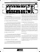
VCM-88 VCM-88E Eight Channel Matrixing Level Controllers RD-8 Desktop Remote RW-8 Wall Mount Remote Operating Manual -6 0 +6 -12 -23 Sig Thr Sig Thr +12 +18 -18 -6 0 +6 -12 -23 Sig Thr -6 0 +6 +12 -12 +18 -18 +23 dBu -23 Sig Thr Sig Thr +12 +18 -18 +23 dBu +23 dBu -6 0 +6 -12 +12 +18 -18 -23 -6 0 +6 -12 -23 Sig Thr +12 +18 -18 +23 dBu -6 0 +6 -12 -23 Sig Thr +12 +18 -18 +23 dBu +23 dBu ∞ On ∞ Gain (dB) ASHLY AUDIO INC.
Operating Manual - VCM-88, VCM-88E, RD-8, RW-8 Level Controllers Table Of Contents 1 Introduction . . . . . . . . . . . . . . . . . . . . . . . . . . . . . . . . . . . . . . . . . . . . . . . . . . . . . . . . . . . . . . . . . . . . . . . 4 2 Unpacking . . . . . . . . . . . . . . . . . . . . . . . . . . . . . . . . . . . . . . . . . . . . . . . . . . . . . . . . . . . . . . . . . . . . . . . . . 4 3 AC Power Requirements . . . . . . . . . . . . . . . . . . . . . . . . . . . . . . . . . . . . . . . . . . .
Operating Manual - VCM-88, VCM-88E, RD-8, RW-8 Level Controllers 10 Troubleshooting Tips . . . . . . . . . . . . . . . . . . . . . . . . . . . . . . . . . . . . . . . . . . . . . . . . . . . . . . . . . . . . . . . 12 10.1 No Output . . . . . . . . . . . . . . . . . . . . . . . . . . . . . . . . . . . . . . . . . . . . . . . . . . . . . . . . . . . . . . . . . . . . 12 10.2 Very Little Output Signal . . . . . . . . . . . . . . . . . . . . . . . . . . . . . . . . . . . . . . . . . . . . . . . . . . . . . .
Operating Manual - VCM-88, VCM-88E, RD-8, RW-8 Level Controllers 1. Introduction 2. Unpacking One of the many useful circuits to be developed for audio use is the VCA, or voltage controlled amplifier. A VCA circuit allows for accurate, low distortion level control without signal degradations encountered when using mechanical controls or long signal paths.
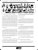
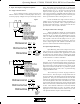
Operating Manual - VCM-88, VCM-88E, RD-8, RW-8 Level Controllers Sig Thr Sig Thr Sig Thr Sig Thr Sig Thr Sig Thr 5. VCM-88, VCM-88E Features 5.1 Signal Present LED Each channel has a green LED to indicate input signal present (app. -20dBu). Since the LED is referencing the audio signal prior to the VCA circuit, the LED will continue flashing even if the channel level is turned down. 5.
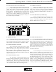
Operating Manual - VCM-88, VCM-88E, RD-8, RW-8 Level Controllers RS-232 CAUTI ON 10 12 10K CW Pin 1-9 RISK OF ELECTRIC SHOCK DO NOT OPEN CAUTION Risk of Electric Shock. Do Not Open VCM-88E Made In USA 5.7 Master Output and Channel Pass Through The VCM-88(E) can be used as an eight-in/oneout remote level control for personal monitor mixing using the Master Output.
Operating Manual - VCM-88, VCM-88E, RD-8, RW-8 Level Controllers 5.13 Data Protocol Selector (VCM-88E only) 5.14 MIDI (VCM-88 only) These two DIP switches allow selection of four data protocols. The Standard protocol is selected for use with current Ashly, AMX, or Crestron controllers. The Protea Software protocol is selected for use with Ashly's Protea System Software. The MIDI protocol is used for control by a MIDI device. The Legacy protocol is selected for control by a legacy Ashly or AMX device.
Operating Manual - VCM-88, VCM-88E, RD-8, RW-8 Level Controllers 7. Audio Connections and Cables 7.1 Balanced and Unbalanced Signals Balanced signal connections are preferred in pro audio applications because of their improved immunity to induced hum and noise. A properly shielded and wired balanced input stage on any product will by design reject most unwanted noise picked up by the cable as well as minimize ground loop problems.
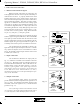
Operating Manual - VCM-88, VCM-88E, RD-8, RW-8 Level Controllers 8. Input and Output Configuration Options: 8.1 Single Connector Insert To use a mixing console’s single jack insert capabilities with the VCM-88, an internal jumper must be selected to properly configure the input and output connecFig 8.1 tions. The jumper must be placed in the “1” position (see drawing at top of page) for single jack in/out operation.
Operating Manual - VCM-88, VCM-88E, RD-8, RW-8 Level Controllers 9. Data Connections and Configurations 9.1 Standard Remote Data Control To connect the RD-8 or RW-8 remote controller, the VCM-88 uses a rear panel female XLR jack, while the VCM-88E uses a three pin euroblock connector. The controller data can be sent through one channel of a standard audio snake without affecting adjacent audio channels. Do not use an isolation transformer in the data line.
Operating Manual - VCM-88, VCM-88E, RD-8, RW-8 Level Controllers 9.5 MIDI Implementation Both the VCM-88 and the VCM-88E can be fully implemented in a MIDI system as a slave unit, that is, able to receive data without being able to generate new data. On the VCM-88, the MIDI Thru jack is a buffered reflection of the MIDI input, and is used to connect to other MIDI devices in the network. On the VCM88E, use the Slave Data In and Out to connect to a MIDI controller.
Operating Manual - VCM-88, VCM-88E, RD-8, RW-8 Level Controllers below). The Slave Data Out from the first unit is connected to the Slave Data In on the next unit, and so on, with the Slave Data Out from the last unit returning to the Slave Data In on the first. A serial RS-232 cable is then connected to the first unit, and the RS-232 switch is set to Multiple RS-232 mode on this first unit only. (Note: the RS-232 switch must be set to standard mode on all other units.
Operating Manual - VCM-88, VCM-88E, RD-8, RW-8 Level Controllers 11. Warranty Information We thank you for expression of confidence in Ashly products. The unit you have just purchased is protected by a limited five year warranty. To establish the warranty, you must first complete and mail the warranty card attached to your product. 12.6 Limiter Threshold Range: -23dBu to +22dBu Compression Ratio: 10:1 12.
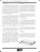
Operating Manual - VCM-88, VCM-88E, RD-8, RW-8 Level Controllers 17.00 (432) 0.10 (2.5) 1.25 (31.8) (44.5) 1.75 1.15 (29) 6.00 (152) 13. Dimensional Drawings Di ensional Dra in or !CM-88 an" !CM-88# in Inches $ % RD-8 Remote Level Control 1.60 R -8 0.38 emote e!el "o$trol 7.94 (202) 0.79 (20) all ount Controller 14.
D21 R12 1M 4148 D22 4148 LM393 U4B + R11 4 4 4 3 4 (AMX) ASHLY 1 2 3 CRESTRON 1 2 3 RS232 1 2 3 MIDI 1 2 ACINLET IEC 320 NEUT X R30 SW2 L SW1 R Q4 D30 R60 2K IN 240V 2 3 L1 12 11 R33 R35 R36 R31 R26 +5 D14 D16 .1U C15 100V 27K U6B 7 -18 C17 C16 1M C14 U7 1.5U D12 1 3 7918 1000 35V 2 D10 - D3 100uF 100V +18 C25 D4 + LM393 U4A 1M 10P R5 C7 D5 4 1 BEAD L2 BEAD Vi 2 3 4148 D9 R7 10.0K 1 VOLT THRESH.
A B C D + - n/c + - G J5 6 5 4 3 2 1 L G N C21 H9 BRACKET 4-40 1 2 C23 BEAD L4 BEAD L1 BEAD L2 ACN out D8 7 17 4 34 33 32 31 30 29 28 27 18 19 2 3 52 43 45 47 49 44 46 48 50 51 C13 18P C8 .1U 2 4 3 5 U9 6N138 10 11 7 12 8 +5 5 8 7 6 2 1 C41 .1U T1 [XFMR-PCB] P85D07106 in=240V 3 2 .
A B C D 1 2 3 4 5 6 + G + G P 2 J101 1 1 2 3 4 5 6 + G + G P 2 J301 1 H340 BRACKET 4-40 R121 100 Out1 O1 1 4 3 2 1 R321 100 Out3 O3 HDRM 1X4 J302 EUROBLOCK 6 OUT IN J306 CH.3 H120 BRACKET 4-40 4 3 2 1 HDRM 1X4 J102 EUROBLOCK 6 OUT IN J106 CH.1 15K 1K R123 R124 -18 12 18K 15K 1K R322 R323 R324 12 13 14 1N4148 D301 1N4148 RATIO 10:1 R326 15K TLE2064 U301D 62K R325 D302 10 1K R305 2 R327 -18 100 Q301 2N4125 U301C 8 10.
A B C D E 1 2 3 4 5 6 + G + G P 2 J501 1 H780 BRACKET 4-40 EUROBLOCK 6 OUT IN + G + G 1 R721 100 Out7 O7 4 3 2 1 P J706 2 J701 1 1 2 3 4 5 6 HDRM 1X4 J702 R521 100 Out5 O5 CH.7 H560 BRACKET 4-40 4 3 2 1 HDRM 1X4 J502 EUROBLOCK 6 OUT IN J506 CH.5 15K 1K R523 R524 -18 12 18K 15K 1K R722 R723 R724 12 13 14 1N4148 D701 1N4148 RATIO 10:1 R726 15K TLE2064 U701D 62K R725 D702 10 1K R705 1K 2 R727 -18 100 Q701 2N4125 U701C 8 10.
A B C 1 H6 BRACKET 4-40 DEVICE ID SW5 SW DIP4 Data J8 EUROBLOCK 3 REMOTE RemotePower 3 2 1 RemoteGround DATAin TXD ConfigB ConfigA R82 2.4K L5 BEAD C25 .001U PROTOCOL SW6 SW DIP2 C26 .001U BEAD L6 2 RS-232 J10 DSUB 9F L7 BEAD 2 X X1 19 3 CONFIG SWITCH 3 .001U .001U C32 C33 G .001U C31 J9 EUROBLOCK 3 100 R83 .001U C30 100 R84 J6B .001U C29 2 of 10s5320b-2.Sch Sheet # 4 J11 EUROBLOCK 6 DC CONTROL A 4 DIP14 [SOCKET] APPROVED: 4 .001U .
VCM R-3 - D12 4148 D11 4148 1M R35 U2A LM393 + R32 10K 18P C19 R39 10K 18P C20 R40 1 51 52 3 2 19 18 17 +5 8 7 1 26 VRL VRH MODA/LIR MODB/VSTBY /IRQ PC0 PC1 PC2 PC3 PC4 PC5 PC6 PC7 STRB/RW STRA/AS PB0 PB1 PB2 PB3 PB4 PB5 PB6 PB7 PE0/AN0 PE1/AN1 PE2/AN2 PE3/AN3 PE4/AN4 PE5/AN5 PE6/AN6 PE7/AN7 PD0/RxD PD1/TxD PD2/MISO PD3/MOSI PD4/SCK PD5/SS 52 PIN PLCC /XIRQ E PA0/IC3 PA1/IC2 PA2/IC0 PA3/OC5/OC1 PA4/OC4/OC1 PA5/OC3/OC1 PA6/OC2/OC1 PA7/PAI/OC1 MC68HC11A1FN /RESET XTAL E