VCM-88C Eight Channel Matrixing Level Controller Operating Manual Ashly Audio Inc. 847 Holt Road, Webster, NY 14580-9103 Toll Free (800) 828-6308, Telephone (585) 872-0010, FAX (585) 872-0739 www.ashly.com All Trademarks referred to herein, are the property of their respective owners.
Page - 2 Operator Manual – VCM-88C Controller This page intentionally left blank Copyright© 2007 – Ashly Audio Inc.
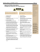
Operator Manual – VCM-88C Controller Page - 3 Important Safety Instructions Consignes de sécurité à lire attentivement Safety Instructions – 3 Introduction - 4 VCM-88C Controller – 5 Connectors & Cables – 5 Physical Description - 6 Installation – 7 Applications - 8 The lightning flash with arrowhead symbol, within an equilateral triangle, is intended to alert the user to the presence of uninsulated "dangerous voltage" within the product's enclosure that may be of sufficient magnitude to constitute a ris
Page - 4 Operator Manual – VCM-88C Controller Safety Instructions – 3 Introduction - 4 VCM-88C Controller – 5 Connectors & Cables – 5 Physical Description - 6 Installation – 7 Applications - 8 Data Connections – 9 Troubleshooting – 11 Dimensions - 11 Specifications - 12 Warranty - 13 Introduction Congratulations on your purchase of an Ashly VCM-88C matrixing level controller.
Operator Manual – VCM-88C Controller Page - 5 Safety Instructions – 3 VCM-88C Controller Introduction - 4 The VCM-88C allows for accurate, low distortion level control without signal degradations encountered when using mechanical controls or long signal paths. This unit adds functionality and control in any system or installation where remote control or fast automatic system response is required. Specific applications are discussed in detail on Page 8.
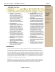
Page - 6 Operator Manual – VCM-88C Controller Safety Instructions – 3 Introduction - 4 VCM-88C Controller – 5 Connectors & Cables - 5 Physical Description The VCM-88C is 1RU, and weighs 10 pounds. VCM-88C Front Panel Physical Description - 6 Front Panel Rear Panel Installation – 7 Applications - 8 1. Data Connections – 9 Troubleshooting – 11 Dimensions - 11 Specifications - 12 Warranty - 13 2. 3. Power LED – This blue LED indicates when the unit is powered on.
Operator Manual – VCM-88C Controller Page - 7 Safety Instructions – 3 VCM-88C Rear Panel Introduction - 4 VCM-88C Controller – 5 Connectors & Cables - 5 1. 2. 3. 4. 5. DC Control - A 12-position Euroblock connector is used for DC control of the eight VCA channels and Master Attenuation, providing a simple and cost-effective method for custom control. Most electronics hardware stores will have the male connector complement.
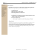
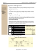
Page - 8 Operator Manual – VCM-88C Controller Safety Instructions – 3 Introduction - 4 VCM-88C Controller – 5 Applications & Configurations Physical Description - 6 To make any configuration changes, the top of the VCM-88C must be removed. Be sure to disconnect all cables & power before opening the unit. Jumper settings are illustrated in the table & diagrams below.
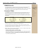
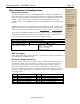
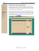
Operator Manual – VCM-88C Controller Page - 9 Data Connections & Configurations Safety Instructions – 3 Introduction - 4 Remote Data Control To connect the RD-8C, RW-8C or other compatible remote controller, the VCM-88C uses a three-pin euroblock connector. Data can be sent through one channel of a standard audio snake without affecting adjacent audio channels. Do not use an isolation transformer in the data line. Connect the three pins to the same pins on the RD-8C/RW-8C remotes as labeled.
Page - 10 Safety Instructions – 3 Introduction - 4 VCM-88C Controller – 5 Connectors & Cables - 5 Physical Description - 6 Installation – 7 Applications - 8 Data Connections – 9 Remote Data Control AMX & Legacy DC Control RS-232 Troubleshooting – 11 Operator Manual – VCM-88C Controller RS-232 Control and Protea System Software Protea System Software is Ashly’s custom Windows program for controlling the Protea family of digital audio processors, as well as the VCM-88C.
Operator Manual – VCM-88C Controller Page - 11 Safety Instructions – 3 Troubleshooting Introduction - 4 Situation Action VCM-88C Controller – 5 No Output Check AC power - is blue power LED indicator on? Check input/output connections - are they reversed? Is the Master Attenuator control turned fully up? Are remote controller channels switched on? Are the input/output jacks configured correctly (one jack insert versus two jacks) for the application? Are the yellow Limiter Threshold indicators on ofte
Page - 12 Safety Instructions – 3 Introduction - 4 Operator Manual – VCM-88C Controller Specifications VCM-88C Connectors & Cables - 5 SPECIFICATION INPUT Input Type: Physical Description - 6 Input Impedance: 20K ohm balanced, 10K ohm unbalanced Installation – 7 Max input level: VCM-88C Controller – 5 Applications - 8 +23dBu Input jack may be internally selected as a single in/out insert Data Connections – 9 CHANNEL OUTPUTS Output Type: Troubleshooting – 11 Output Impedance: Dimensions - 11
Operator Manual – VCM-88C Controller Page - 13 Introduction Safety Instructions -2 –3 Limited Warranty The PE Series Introduction - 4- 3 Warranty service for this unit will be provided by ASHLY AUDIO INC. in accordance with the following warrant statement. ASHLY AUDIO INC. warrants to the owner of this product that this product and the components thereof, will be free from defects in workmanship and materials for a period of FIVE years from the date of purchase. ASHLY AUDIO INC.
Copyright© 2007 – Ashly Audio Inc.