XR-1001 XR-2001 XR-4001 Electronic Crossovers Operating Manual Ashly Audio Inc. 847 Holt Road, Webster, NY 14580-9103 Toll Free (800) 828-6308, Telephone (585) 872-0010, FAX (585) 872-0739 www.ashly.com All Trademarks referred to herein, are the property of their respective owners.
Page - 2 Operator Manual – XR Series Crossovers This page intentionally left blank Copyright© 2006 – Ashly Audio Inc.
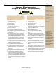
Operator Manual –XR Series Crossovers Page - 3 Important Safety Instructions Consignes de sécurité à lire attentivement Safety Instructions – 3 Introduction – 4 XR Crossovers – 5 Connectors & Cables – 5 Physical Description – 6 Installation – 7 The lightning flash with arrowhead symbol, within an equilateral triangle, is intended to alert the user to the presence of uninsulated "dangerous voltage" within the product's enclosure that may be of sufficient magnitude to constitute a risk of electric shock t
Page - 4 Operator Manual – XR Series Crossovers Safety Instructions – 3 Introduction – 4 About Ashly XR Crossovers – 5 Connectors & Cables – 5 Physical Description - 6 Installation – 7 Typical Applications - 8 Troubleshooting - 10 Introduction Congratulations on your purchase of an Ashly XR Crossover. This crossover is the product of an intensive research effort which combined a reexamination of traditional crossover theory with practical field use.
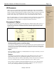
Operator Manual –XR Series Crossovers Page - 5 Safety Instructions – 3 XR Crossovers Introduction – 4 Ashly crossovers are based upon a powerful state-variable filter circuit, which guarantees that two adjacent frequency band outputs always remain in phase. These crossovers offer a number of useful and unusual features, including continuous tuning, a response control, and a unique output stage, which maintains low noise at any level setting.
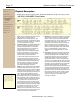
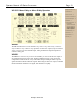
Page - 6 Operator Manual – XR Series Crossovers Safety Instructions – 3 Introduction – 4 XR Crossovers – 5 Connectors & Cables–5 Physical Description The XR-1001 is 1RU, and weighs 8 pounds. The XR-2001 & XR-4001 are 2RU, and weigh 11 pounds. XR-1001 & XR-4001 Front Panels Physical Description – 6 Front Panels Rear Panels Installation – 7 Typical Applications - 8 Troubleshooting - 10 Dimensions - 10 Specifications - 11 Warranty - 12 1.
Operator Manual –XR Series Crossovers Page - 7 XR-1001, XR-2001 and XR-4001 Rear Panels Safety Instructions – 3 Introduction – 4 XR Crossovers – 5 Connectors & Cables–5 Physical Description – 6 Front Panels Rear Panels Installation – 7 General Requirements AC Power Typical Applications - 8 Troubleshooting - 10 Dimensions - 10 Specifications - 11 Warranty - 12 1. Inputs - For unbalanced inputs, the signal should be on the + connection and the connection tied to ground.
Page - 8 Operator Manual – XR Series Crossovers Safety Instructions – 3 Introduction – 4 Typical Applications XR Crossovers – 5 The following information will help you make the most of your new crossover: Connectors & Cables–5 Connecting to a Sound System Physical Description – 6 Installation – 7 Typical Applications – 8 Connecting Speaker Placement XR1001 Operation XR2001 Operation XR4001 Operation Troubleshooting - 10 Dimensions - 10 Specifications - 11 Warranty - 12 Usually, the output signal fr
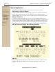
Operator Manual –XR Series Crossovers XR 2001 Mono 4-Way or Mono 5-Way Operation Page - 9 Safety Instructions – 3 Introduction – 4 XR Crossovers – 5 Connectors & Cables–5 Physical Description – 6 Installation – 7 Typical Applications – 8 Connecting Speaker Placement XR1001 Operation XR2001 Operation XR4001 Operation Troubleshooting - 10 Dimensions - 10 Specifications - 11 Warranty - 12 XR2001 The XR 2001 functions as a four channel 2-way, stereo 3-way, mono 4-way, or mono 5way.
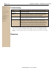
Page - 10 Operator Manual – XR Series Crossovers Safety Instructions – 3 Introduction – 4 Troubleshooting XR Crossovers – 5 Situation Action Connectors & Cables–5 No Output Check AC power - is LED indicator on? Check in/out connections, are they reversed? Are you sure you have input signal? Peak light flashes frequently The level is too high somewhere in the crossover. Try turning down individual output levels and then the input until the peak LED stays off.
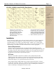
Operator Manual –XR Series Crossovers Page - 11 Specifications Safety Instructions – 3 XR 1001 - to +8.5 dB XR 2001 - to +8.5 dB XR 4001 - to +8.5 dB Damping/Response 2dB – 12dB 2dB – 12dB 2dB – 12dB Output Level Control - to +15 dB - to +15 dB - to +15 dB 20K Balanced 20K Balanced 20K Balanced 100 Servo Balanced +23 dBu 100 Servo Balanced +23 dBu 100 Servo Balanced +23 dBu +23 dBu +23 dBu +23 dBu ±0.5dB 20Hz-20kHz ±0.5dB 20Hz-20kHz ±0.5dB 20Hz-20kHz <0.
Page - 12 Operator Manual – XR Series Crossovers Safety Instructions – 3 Introduction – 4 XR Crossovers – 5 Connectors & Cables–5 Physical Description – 6 Installation – 7 Typical Applications – 8 Troubleshooting - 10 Dimensions - 10 Specifications - 11 Warranty - 12 Limited Warranty Warranty service for this unit will be provided by ASHLY AUDIO INC. in accordance with the following warrant statement. ASHLY AUDIO INC.
Operator Manual –XR Series Crossovers All Rights Reserved Page - 13