
Instruction manual


Page 150 Z-12 Real-Time Sensor Operation and Reference Manual
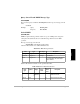
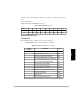
Table 4.105 defines the data that will repeat for each satellite whose corresponding bit
in PRN is 1.
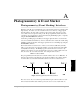
Zeros are padded so that all of the <packed data> will be a module of 16 bits. Total
number of bits in <packed data>:ceil((94 + 72*2*N
SVS
)/16*16 and
<data length> = ceil ((94 + 72*2*N
SVS
)/16)*2
long PRN 32 SVPRN for the satellites which
have data in this message. It is a
bitwise indication. Starting from
the LSB, bit 1 corresponds to
SVPRN #1, bit 2 to SVPRN #2,
and so on. Bit value of 1 means
that SVPRN has data in
message; otherwise 0.
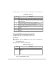
Table 4.105: PRN Data Structure
Data
Type
Symbol Range
Reso-
lution
Compress
Num. BIts
Description
double PL1 1.0e-10
seconds
31 Pseudorange in units of 1.0e-10
seconds (or 01. nanoseconds).
Multiply this value by 1.0e-10 to
get pseudorange in seconds. A
zero value indicates bad
pseudorange.
char WN 1 Warning bit
1=bad carrier phase and possible
cycle slip
0=good carrier phase
Sign 1 2 Carrier phase sign bit
1=negative carrier phase value
0=positive carrier phase value
long PH_I 1 28 Integer part of carrier phase
measurement in cycles
double PH_F 15.0e-4 11 Fractional part of the carrier phase
measuement in units of 5e-4 cycles.
Multiply this number by 5e-4 to get
fractional carrier phase
measurement = PH_I + PF_F*5.0e-
4.
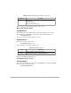
Table 4.104: Packed Data Field Structure (continued)
Data
Type
Symbol Range
Reso-
lution
Compress
Num.
Bits
Description