
Instruction manual

Operation Page 9
Operation
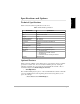
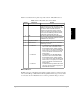
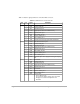
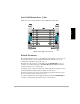
Table 2.1 describes the front panel components of the Z-12 Real-Time Sensor.
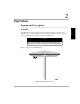
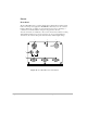
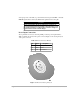
RF Connector
The RF connector is a standard N-type female receptacle wired for connection via 50-
ohm coaxial cabling to a GPS antenna with integral LNA. The N-type connector shell
is connected to the Z-12 Real-time Sensor common ground. The N-type connector
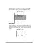
Table 2.1: Z-12 Real-Time Sensor Front Panel
Number Component Function
1 Antenna RF connector The RF connector is a standard N-type female
receptacle wired for connection via 50-ohm coaxial
cabling to a GPS antenna with an integral LNA. The N-
type connector shell is connected to the Sensor
common ground. The N-type connector center pin
provides +9.5 VDC (to power the LNA) and accepts
1227 and 1575.42 MHz RF input from the antenna;
the RF and DC signals share the same path.
2 LED LED which provides equipment status. Red indicates
power is applied. Green flashes indicate the number of
satellites the Sensor has acquired.
3 On/Off Power Button Turns unit on and off.
4 PWR Connectors Dual power connector which provide connections to
redundant power sources.
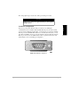
5 Serial Port A
Serial Port B
Serial Port C
A complete RS-232 port with full-handshaking.
Port A can be used for communications with a
Husky hand-held computer, an IBM compatible
PC, or a radio. Port A is used for transferring data
from the receiver to a computer, from a receiver to
a receiver, and all other communications to and
from the receiver.
A complete RS-232 port with full-handshaking.
Port B can be used for communication with the
Husky hand-held computer, an IBM compatible
PC, or a radio. Port B is used for transferring data
from the receiver to a computer, from a receiver to
a receiver, and all other communications to and
from the receiver.
An abbreviated RS-232 port that has flow-control
only. Port C can only be used for input/output of
RTCM differential corrections.