
Instruction manual


Page 20 Z-12 Real-Time Sensor Operation and Reference Manual
Hardware Setup
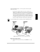
In the following setup, port B for both base Sensor and rover Sensor will be used for
differential data link, while port A will be used for connecting to a PC and Sensor
serial control.
1. Connect all the cables for the base Sensor and the rover Sensor as described
in “Hardware Setup” on page 14.
2. Connect the port B of both base Sensor and the rover Sensor with provided
serial cable.
A typical differential system is depicted in Figure 2.6.
In this manual, the word “remote” or “rover” share the same meaning. They are often used
interchangeably.
Entering Base Station Coordinates
This is a common procedure for any base station setup. The coordinates can be
entered at any mode, even if the Sensor is not configured in the RTCM base or CPD
base mode.
When operating the system in RTCM message format, the base station coordinates must be entered
as the antenna phase center position. While operating the system in CPD DBEN message format, the
base station coordinates can be entered either as the antenna phase center position and zeros out all
the antenna offset parameters, or one can enter the base station coordinates of the ground mark and
enter proper antenna offset parameters.
Entering Known Coordinates
If you know the WGS-84 coordinates where the base station antenna is located, enter
the latitude, longitude, and the ellipsoidal height via the following commands.
$PASHS,POS,3722.3882335,N,12159.8353120,W,-5.1238.
To verify the entered coordinates, type $PASHQ,POS, the Sensor will response
$PASHR,POS,3722.3882335,N,12159.8353120,W,-5.1238*33
Or you can set each latitude, longitude, or ellipsoidal height via $PASHS,LAT, $PASHS,LON,
$PASHS,ALT, respectively. Refer to Chapter 4, Command Response Formats for more
detai l.