Installation Guidelines Patio Doors Inswing / Outswing / Entry / Sliding Patio Door 900 South 19th Street West Des Moines, IA 50265 800.935.2000 www.ashworthdoors.
Installation Guidelines for Ashworth Patio Doors Installer • Read instructions completely before attempting installation. Failure to follow these guidelines will forfeit the Ashworth warranty coverage, written or implied. • Always provide a copy of these instructions to the homeowner. • These instructions are consistent with ASTM 2112 “Standard Practice for Installation of Exterior Windows, Doors and Skylights” into common wall constructions.
Tools Needed Materials Needed • acker Rod B – 1/4"-1/2" diameter closed cell foam • I nsulation – Minimally expanding low pressure polyurethane window and door foam • S hims – Made of cedar or synthetic material • 2-1/2" Drywall Screws – (No Nail Fin Installation) Ladder / Scaffolding • oofing Nails (Nail Fin Installation) R – 2" Galvanized (16D) • Square • • Tape Measure S ilicone Sealant – 100% Silicone • • Stapler F lashing (Nail Fin Installation)
int eXT fig. 1 int eXT fig. 3 fig. 2 fig. 4 Step 3: Flashing the Sill A) IMPORTANT! a. Use flashing that is 6" minimum in width. b. Flashing must meet ASTM-D779 performance requirements. B) Measure the width of the rough opening. Cut a length of flashing that is 12" wider than the rough opening. This will allow you to run the flashing 6" up each side. C) Cut 1-1/2" slits at each end of the flashing as shown below. (Fig. 5) 6" minimum 1-1/2" 6" 1/2" fig.
Step 4a: Nail Fin Door Installation (Go to Step 4b for No Nail Fin Installation) A) Remove all packaging material (blocks, pads, protectors, stretch wrap, nail fin). B) Inspect and verify the following: a. The door unit is the correct size and configuration. b. The unit is free from any damage or defects. C) Contact your nearest Ashworth distributor if there are any problems with step B above. D) Install the supplied nail fin to both sides and top of the door as shown below.
I) Apply sealant to sill rough opening: a. Apply three 1/4" continuous beads of silicone across the entire width of the rough opening. Note the locations are different for each door type. Fig. 13 shows the silicone location for a 4-9/16" and 6-9/16" inswing door. The bead location will be different for other jamb sizes. (Fig. 12 & 13) 4 14" (4 169 " FRAME) 6 14" (6 169 " FRAME) SEALANT FIG. 12: OUTSWING PATIO SILL J) K) L) M) N) O) FIG. 13: 4-9/16" & 6-9/16" INSWING PATIO DOOR SILL b.
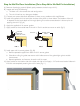
each side jamb and three equally spaced points along the head jamb. Then drill a 1/8" pilot hole through the entire unit at each of the 11 marked places. (Fig. 16) E) After the pilot hole has been created, drill a 25/64" hole through the aluminum cladding only. (Fig. 16) F) Test fit the unit in the rough opening and set the unit to the appropriate jamb depth. Once the correct jamb depth has been determined, draw a line along the inside of the sill on the subfloor. (Fig. 17) 1/8" DIA.
M) Screw all four corners in place through the pre-drilled holes in the frame. N) Finish screwing the door to the rough opening. Apply a screw through all 11 pre-dilled frame holes. Step 5: Secure Hinge and Verify Operation A) Apply the supplied #12 x 2-1/4" screws through each hinge securing the hinges and frame to the rough opening. Additional shims are required behind each hinge. (Fig. 21) B) Verify the operation of the door is correct.
Step 7: Complete Flashing (Nail Fin Installation Only) A) Cut and apply side flashing. Side flashing should run from the bottom of the sill flashing to 4" above the rough opening. (Fig. 26) B) If non-adhesive flashing is used, make sure all staple holes are sealed with silicone. C) Cut and apply head flashing. The head flashing should run slightly past the edge of the side flashing as shown. (Fig. 27) D) Flip down the top flap of the WRB. (Fig. 28) E) Tape the cut seams of the WRB. (Fig. 29) FIG. 26 FIG.
SHIM & INSULATION SHIM & INSULATION 1/4" MIN. SEALANT & BACKER ROD 1/4" MIN. FIG. 32: SIDe JAMB – NO NAIL FIN INSTALLATION FIG. 33: HeAD JAMB – NO NAIL FIN INSTALLATION Step 9: Completing the Installation A) Remove all labels or shipping materials. B) Hinge adjustment may be required to complete the installation. (Fig. 34) Top hinge adjusts a. When adjusting the hinge, use a hand screwdriver. horizontally b. Use the top and bottom hinge to adjust the door panel horizontally. c.