
User's Manual


Note: Bit 7 CAN refer to Card Application Number found on Ez-Link card.
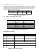
Bit
Bit 1
Bit 2
Bit3
Bit4
Bit5
Bit6
Bit7
Bit 8
Label
A0
A1
A2
A3
Refers to Table 3 for other DIP Switch
Setting.
Hex
Address
80
0
0
0
0
1
81
1
0
0
0
1
82
0
1
0
0
1
83
1
1
0
0
1
84
0
0
1
0
1
85
1
0
1
0
1
86
0
1
1
0
1
87
1
1
1
0
1
Table 4 RS485 Readers Address Dip Switch Setting
Table 5 Wiegand bit format Dip Switch setting
Note : Since the Contactless SmartCard CSN is 32 bit can be up to 10 digits decimal when converted. This is
the solution to truncate the CSN and provide a result that once converted, it only give maximum of 8-digit
decimal. The 37 bit odd and even priority bit is a result of getting the first and second half of total bit length.
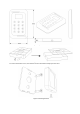
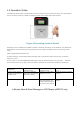
1.4 Installation and Mounting Instruction
Identify the reader mounting location. The reader may install onto any surface, including metal.
Remove the snap on cover and use the reader as a template, draw the mounting hole position onto the
mounting surface. Drill 2 appropriate holes to install the reader.
Drill a 25mm hole for the cable.
Connect the external (site) cable to the terminal block on the reader according to the wiring code below.
Double-check the wiring connection.
Replace the snap on cover and tighten it with the screw provided.
Switch on the power to test the reader and observe.
DIPSW
DIP1
DIP2
DIP3
DIP4
DIP5
DIP6
DIP7
DIP8
Bit Format
Wiegand setting
OFF
Wiegand
26bit
off
off
off
off
Wiegand
=Off
off =
64bit
RS485
on=
32bit
RS485
off =
CSN
RS485
on =
CAN
RS485
off =
Run
on=
test
32bit
on
off
off
off
32bit(8bit)
off
on
off
off
34bit
on
on
off
off
37bit
off
off
on
off
37(8digit)
on
off
on
off
40bit
off
on
on
off
40bit(8digit)
on
on
on
off
56bit
off
off
off
on
64bit
on
off
off
on
80bit
off
on
off
on
168bit(ASIS)
on
on
on
on