
User's Manual


1.5 Operation Guide
The AMR170 series reader must work with the ACU controller (it cannot operate by itself). The reader allows
user to access by Card only, Details of operation please refer to IBSS and/or ACU manual.
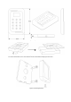
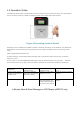
Figure 4 Presenting Cards to Reader
Keeping the card in parallel to the AMR17x reader a maximum read range can be obtained. The Reader will
still be able to read Card when the card is presented at an angle but this will result in the reducing of read
range.
Card and PIN operation (Model 175)
a) When the Green Led is blinking after presenting card, the means that PIN is request. Key in PIN and
follows by “#” key
b) Key in PIN + 1 for PIN DURESS (Example PIN is 1234, for duress activation, key pin 1235) Note that
the maximum PIN is up to 6 digit. When the reader is powered-up, the LED and the Buzzer will respond.
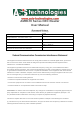
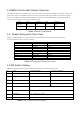
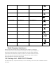
c) Reader Alarm & Event Message on LCD Display (AMR175 only)
Description
Buzzer response
(AMR171/175)
LED Response
(AMR171/175)
LCD Display (For AMR175
only)
a) Upon Power Up the
Reader **N is setting on
the DIP switch.
The buzzer will beep
(N+1) time accord to the
DIP switch setting
Reader’s Amber LEDs
Blink (N+1) times
Model No Reader Address
Version
b) Reader Ready
Silent
Red LED always ‘ON’
Green LED Short blink
at every 3 secs interval
DD/MM/YY / 00:00:00
Ready