USER GUIDE IMPACT 64 Not the actual front page 801.200A USG/064/AE-A 14.06.
USER GUIDE IMPACT 64
USER GUIDE LCD PANEL 2
USER GUIDE LCD PANEL TABLE OF CONTENTS INTRODUCTION ..................................................................................... 5 MAIN FEATURES .................................................................................... 5 SUPPLIED MATERIAL............................................................................. 6 OPTIONAL MATERIAL ............................................................................ 6 SETTING UP THE LCD PANEL ..................................................
USER GUIDE LCD PANEL This publication is printed on recycled paper. The information contained in this user guide is preliminary, and the products described herein are subject to change without prior notice. The symbols and are used in this publication to indicate Warning and Note respectively.
USER GUIDE 1 LCD PANEL INTRODUCTION The LCD panel is a state of the art projection device that can be connected to most computers. The ability to display a multitude of greyshades simultaneously, makes it the ideal choice for presenting computer generated text and graphics. Applications include presentations, software training, educational use, advertising, information boards and other situations where a small or large audience shares information.
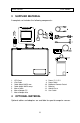
USER GUIDE 3 LCD PANEL SUPPLIED MATERIAL A complete set includes the following components : 1. 2. 3. 4. 5. 6. 7. 4 LCD Panel VGA-Cable Cable-Adapt. MACII mon Cable-Adapt. MACII comp. Mouse Cable Mouse Adapter PC Mouse Adapter Mac 8. 9. 10. 11. 12. 13. Power -5, 12, 5 V Power Cable BatMouse Remote Control Batteries Attachè Case User Guide OPTIONAL MATERIAL Optional cables and adapters are available for special computer sources.
USER GUIDE 5 LCD PANEL SETTING UP THE LCD PANEL Switch off all equipment before connecting the components. Be aware of static electricity that may build up, especially in the dry season and when operating on synthetic carpets. Discharge any static electricity by touching a metallic surface before you start. Place the LCD panel on top of a transmissive overhead projector (OHP). Select a high intensity type projector, for instance 400W.
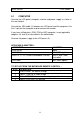
USER GUIDE 5.1 LCD PANEL COMPUTER Connect the LCD panel, computer, monitor and power supply as shown in the rear foldout. Connect the VGA cable (1) between the LCD panel and the computer. Use the Y-split on the computer end to connect the monitor. If you have a Macintosh, EGA, CGA or NEC computer, insert applicable adapters (4) and (5) as described in the table below. Connect the power supply to the LCD panel (3). APPLICABLE ADAPTERS : COMPUTER VGA/SVGA EGA/CGA* MACII c../v..
USER GUIDE 5.2 LCD PANEL MOUSE See the rear foldout when setting up. Connect the mouse to the LCD panel using the appropriate adapter (6) as described in the table below. Then connect the adapter (6) to the mouse cable at the computer end. Finally, connect the mouse cable to the LCD panel (2). For the computer to recognise the mouse, connect all cables and power on the LCD panel before power is applied to the computer.
USER GUIDE LCD PANEL If double-click does not work properly, try to adjust the double-click rate within the computer application in use.
USER GUIDE 6 LCD PANEL USING THE LCD PANEL The LCD panel has a set of connectors and controls that you need to know in order to operate the device correctly. 6.1 REMOTE CONTROL The infrared BatMouse remote control (RC) is the main user interface to the device. The RC is used to set the LCD panel correctly (to get the best possible viewing conditions) and to control the presentation. The figure shows the different keys of the BatMouse.
USER GUIDE LCD PANEL The 'MEM' column in the table below indicates whether the setting is memorized for each source. For a detailed overview, see the Features section.
USER GUIDE 6.2 LCD PANEL FRONT PANEL The front panel keyboard consists of a subset of the remote control keys. ON/OFF CONTROL TUNE BRIGHT RESET ON/OFF 6.3 TUNE BRIGHT RESET FUNCTION Adjusts the stability of the image Adjusts the brightness (whiteness) of the image Defaults to factory settings LED activity indicator CONNECTORS All connectors are positioned on the right hand side of the LCD panel. See the technical data section for pinouts of the various connectors.
USER GUIDE 7 LCD PANEL FEATURES The LCD panel has a variety of different features implemented. This chapter explains each feature in detail. 7.1.1 INTELLIGENT SAFECOOL SYSTEM The fan operation is controlled by the overhead projector light (OHP). This safety feature ensures that the fan is always operating as long as the OHP is turned on. When the OHP is turned off, the fan automatically stops to minimize noise. The power supply must be attached to the panel for the fan to work properly. 7.1.
USER GUIDE LCD PANEL 7.1.4 SVGA SVGA in 800 x 600 mode is compressed both horizontally and vertically to 640 x 480 resolution. This feature is convenient when displaying irregular images (like pictures, scanned images and coarse graphics). Regular images (patterns, text and fine line graphics) may look distorted due to the downsizing. In this case, we recommend setting up the computer in 640x480 mode for a precise image. 7.1.
USER GUIDE LCD PANEL 7.1.10 RESET This feature resets most controls to standard settings. See the 'MEM' column in the remote control description, where YES indicates a standard resettable setting. RESET will only reset the active mode. A fundamental master reset may be performed by pressing all four front panel keys simultaneously for approx. 5 seconds. All settings will return to factory defaults. Do not perform a master reset unless it is really required.
USER GUIDE LCD PANEL 7.1.16 FREQUENCY This setting is usually not changed by the user. It is however provided in case of adaptation to special graphics adapters that are close to those in the compatibility list. A bad frequency setting can be seen as an image too wide or too narrow, combined with vertical, unstable bands. Press the FREQUENCY keys left or right to correct the image. The setting is stored individually for each source. 7.1.
USER GUIDE 8 LCD PANEL PRACTICAL HINTS AND TIPS This is a list of what to do when things go wrong. Check the symptoms carefully if you experience any problem. The cure may be at your hands! Always press the RESET key and observe that the LED on the LCD panel is flashing. This indicates that the LCD panel receives signals from the remote control..
USER GUIDE LCD PANEL The remote control is not working - Check if the batteries need replacement - Be sure to point at the projection screen or directly at the IR eye in the front of the LCD panel - You may be too far away from the panel (max.
USER GUIDE 9 LCD PANEL MAINTENANCE From time to time, the housing and protection glasses may be cleaned with a damped, non abrasive cloth, possibly using a mild detergent to remove spots. The upper protection glass is not removable, as it only needs cleaning from the outside (the inside is sealed to the LCD module). The lower protection glass can be removed for cleaning. Place the unit upside-down on a soft cloth to avoid scratches.
USER GUIDE LCD PANEL 11 TECHNICAL DATA The technical data may change without prior notice in order to improve the product performance. The apparatus is designed for indoor use and should not be operated outside the general environmental limits, as this may lead to permanent damage and violation of any warranties. 11.1.
USER GUIDE LCD PANEL 11.1.2 DISPLAY UNIT Monochrome display unit connecting directly to external video sources. SIZE WEIGHT POWER LCD CELL GREYSHADES RESPONSE TIME CONTRAST RATIO PIXEL RESOLUTION SCREEN DIAGONAL MOUSE COMPATIBILITY VIDEO FREQUENCY HORIZONTAL SYNC VERTICAL SYNC COMPUTER INPUT APPROVALS 310 x 310 x 40 mm 12.2 x 12.2 x 1.6 inch 2200 grams 4.9 pounds Power -5, -12, 5 V (Universal) Dual scan FSTN 64 130 ms 20:1 640 x 480 9.
USER GUIDE LCD PANEL 11.1.3 POWER SUPPLY Primary switched universal type AC to DC converter. INPUT VOLTAGE OUTPUT VOLTAGES CONNECTOR APPROVALS 100 to 250 VAC +5VDC, +12VDC, -5VDC 5 pin DIN male TÜV, UL, CSA, N, S, D, FI 11.1.4 REMOTE CONTROL Infrared wireless remote control. BATTERIES RANGE 2 pcs LR03/AAA 1.5V penlight 7m 23 feet 11.1.5 COMPATIBILITY The unit is predefined for the following interfaces.
USER GUIDE LCD PANEL 12 CONNECTORS The pinouts of all external connectors are described. 12.1.1 POWER This connector feeds regulated DC power to the panel. 2 4 5 1 3 1 2 3 4 5 5 PIN DIN FEMALE (FRONT VIEW) GND GND +5VDC -5VDC +12VDC 12.1.2 MOUSE This connector is used for mouse control. 7 8 6 5 4 2 3 1 2 3 4 8 PIN MINIDIN FEMALE (FRONT VIEW) MAC ADB PS/2 CLOCK PS/2 DATA RS232 TXD 5 6 7 8 RS232 RTS RS232 RXD RS232 CTS GND 1 12.1.
USER GUIDE LCD PANEL 13 FCC STATEMENT This equipment has been certified to comply with the limits for a Class A computing device, pursuant to Subpart J of Part 15 of FCC rules. Only peripherals (computer input/output devices, terminals, printers, etc.) certified to comply with the Class A limits may be attached to a computer that complies with Class A limits. When connecting to a peripheral device, a shielded input/output cable is required to ensure compliance with FCC rules.
USER GUIDE LCD PANEL 14 ENVIRONMENTAL STATEMENT This product is manufactured to minimize the stress and pollution of the surroundings. Where possible, recyclable materials are used. ITEM PACKAGING MECHANICS ELECTRONICS LCD MODULE RECYCLING / HANDLING Only recyclable materials are used Only recyclable plastics and metal is used. Recycling codes are moulded in the plastic. Metal parts are painted aluminium and steel. No CFC is used during manufacture. No components that require special handling are used.
USER GUIDE LCD PANEL 15 SERVICE INFORMATION In cases where a problem cannot be solved by the assistance of your dealer, please call the following number to get an RMA (Return Authorization Number) : +47 69 34 01 55 (Norway) To return the defective unit, package well (preferably using the original packaging material), enclose a copy of your sales receipt and a description of the problem you experience, and ship prepaid to : ASK AS Customer Service Department RMA ................
USER GUIDE LCD PANEL 16 CONNECTION LAYOUT The foldout shows how to connect the LCD panel to the different computer sources.