CABLE SATELLITE TELECOM TERRESTRIAL DWG855 - Residential Voice Gateway User manual
CAUTION CAUTION Disconnect power before To ensure reliable operation and to prevent overheating, servicing. provide adequate ventilation for this modem and keep it away from heat sources. Do not locate near heat registers or other heat-producing equipment. Provide for free air This device is intended for flow around the Residential Voice Gateway and its power indoor operation only. supply. Telephone jacks Line 1 and Line 2 must not be connected to outside wiring.
PacketCable and DOCSIS compliant This product was designed according to Data over Cable Service Interface Specifications and PacketCable Voice Over IP Cable Telephony Specifications. It will operate on any DOCSIS-compliant Hybrid Fiber Coax (HFC) cable system and offers DOCSIS and PacketCable Baseline Privacy to promote secure internet transactions and PC-secure telephone service.
Chapter 1: Connections and Setup Chapter 1: Connections and Setup .................................................................................................... 4 Introduction ................................................................................................................................ 4 Residential Voice Gateway Features ........................................................................................... 4 What’s on the CD-ROM .................................................
Chapter 1: Connections and Setup 1. Software ........................................................................................................................ 20 2. Connection ..................................................................................................................... 21 3. Password ........................................................................................................................ 22 4. Diagnostics .........................................................
Chapter 1: Connections and Setup Basic Setup ........................................................................................................................ 42 Gateway – Wireless Web Page Group .............................................................................................. 43 1. Radio ............................................................................................................................ 44 2. Primary Network .......................................................
Chapter 1: Connections and Setup Chapter 1: Connections and Setup Introduction Residential Voice Gateway Features Support Multiple Provisioning Mode 4 Standard RJ-45 connectors for 10/100BaseT Ethernet with auto-negotiation and MDIS functions Two RJ-11 Foreign Exchange Station (FXS) ports for IP telephony IEEE 802.
Chapter 1: Connections and Setup Links to RCA or Thomson web sites DOCSIS and PacketCable are trademarks of Cable Television Laboratories, Inc.
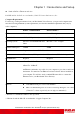
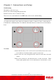
Chapter 1: Connections and Setup Wall Mounting The number of the screw: 2 pcs Direction for wall mounting: LED panel upward. Dimension for the screw: 4.4 mm (0.17 inch) There are 4 slots on the underside of the EMTA that can be used for wall mounting. Note: When wall mounting the unit, ensure that it is within reach of the power outlet. You will need 2 suitable screws which screw diameter would be 4.4 mm (0.17 inch) to wall mount the Cable Modem or the Battery Pack.
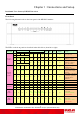
Chapter 1: Connections and Setup Residential Voice Gateway DWG855 Overview Front Panel The following illustration shows the front panel of the DWG855 machine: The LEDs on the front panel are described in the table below (from left to right): DWG855T/ DWG855CH Power ON Boot-up Operation Internet Ethernet DS US Online ON ON ON ON 0.
Chapter 1: Connections and Setup DWG855T/ DWG855CH Battery Good Power Internet Ethernet Tel 1 Tel 2 ON FLASH ON ON ON FLASH DS US Online 1 2 3 4 ON AC Good Battery Low Wireless Operation> Description Tel1 Off-hook, Tel2 On-hook Tel1 On-hook, Tel2 Off-hook FLASH FLASH Both Lines Off-Hook ON ON ON Both Lines On-Hook ON FLASH ON Tel1 Off-hook, Tel2 On-hook ON ON FLASH FLASH ON AC Good Battery Bad Battery Tel1 On-hook, Tel2 Off-hook FLASH FLASH Both Lines Off-Hook ON
Chapter 1: Connections and Setup Rear Panel TEL1 & TEL2 Telephony RJ-11 connector ETHERNET 1-4: Ethernet 10/100BaseT RJ-45 connector REBOOT EMTA: Reboot this Residential Voice Gateway CABLE: F-Connector 15VDC: Power connector Installing the Battery This section provides information on installing batteries into the modem. Follow the steps below: 1. Ensure the power cord is unplugged. 2. Remove the battery cover on the rear panel. There are two battery compartments.
Chapter 1: Connections and Setup Flank Panel WPS: WiFi Protected Setup 10 Illustrations contained in this document are for representation only.
Chapter 1: Connections and Setup Relationship among the Devices This illustration shows a cable company that offers DOCSIS- and PacketCable-compliant voice/data services. What the Modem Does The Residential Voice Gateway provides wired and wireless high-speed Internet access as well as cost-effective, toll-quality telephone voice and fax/modem services over residential, commercial, and education subscribers on public and private networks via an existing CATV infrastructure.
Chapter 1: Connections and Setup you need to install special software or re-configure your computer to make your cable internet service work for you. Contact Your Local Cable Company You will need to contact your cable company to establish an Internet account before you can use your gateway.
Chapter 1: Connections and Setup Connecting the Residential Voice Gateway to a Single Computer This section of the manual explains how to connect your Residential Voice Gateway to the Ethernet port on your computer and install the necessary software. Please refer to Figure 1 to help you connect your Digital Cable Modem for the best possible connection. Attaching the Cable TV Wire to the Residential Voice Gateway 1. Locate the Cable TV wire. You may find it one of three ways: a.
Chapter 1: Connections and Setup Below are important points to remember before you connect the Residential Voice Gateway. For Ethernet connections, go to page 14. For telephone and fax connections, go to page 16. Ethernet Connection to One Computer Make the connections to the modem in the following sequence: 1. Connect one end of the coaxial cable to the cable connection on the wall, and the other end to the CABLE jack on the Residential Voice Gateway. 2.
Chapter 1: Connections and Setup Connecting More Than Two Computers to the Residential Voice Gateway If you need to connect more than two computers to DWG855, simply connect the computers to the Ethernet ports on the rear panel. Fig.3: Multiple-PC Connection Note: You may need to check with your service provider in order to connect multiple computers. 15 Illustrations contained in this document are for representation only.
Chapter 1: Connections and Setup Telephone or Fax Connection When properly connected, most telephony devices can be used with the Residential Voice Gateway just as with conventional telephone service. To make a normal telephone call, pick up the handset; listen for a dial tone, then dial the desired number. For services such as call waiting, use the hook switch (or FLASH button) to change calls.
Chapter 1: Connections and Setup Activating the Residential Voice Gateway After installing the Residential Voice Gateway and turn it on for the first time (and each time the modem is reconnected to the power), it goes through several steps before it can be used. Each of these steps is represented by a different pattern of flashing lights on the front of the modem. Note: All indicators flash once before the initialization sequence.
Chapter 2: Web Configuration Chapter 2: Web Configuration To make sure that you can access the Internet successfully, please check the following first. 1. Make sure the connection (through Ethernet) between the Residential Voice Gateway and your computer is OK. 2. Make sure the TCP/IP protocol is set properly. 3. Subscribe to a Cable Company.
Chapter 2: Web Configuration Outline of Web Manager The main screen will be shown as below. Fig. 6 Outline of Web Manager Main Menu: the hyperlinks on the top of the page, including Gateway, VoIP and several sub-menu items Title: the sidebar on the left side of the page, indicates the title of this management interface, e.g.
Chapter 2: Web Configuration Gateway - Status Web Page Group 1. Software The information section shows the hardware and software information about your gateway. The status section of this page shows how long your gateway has operated since last time being powered up, and some key information the Cable Modem received during the initialization process with your cable company. If Network Access shows “Allowed,” then your cable company has configured your gateway to have Internet connectivity.
Chapter 2: Web Configuration 2. Connection This page reports current connection status containing startup procedures, downstream and upstream status, CM online information, and so on. The information can be useful to your cable company’s support technician if you’re having problems. Fig. 8 Gateway\Status\Connection 21 Illustrations contained in this document are for representation only.
Chapter 2: Web Configuration 3. Password This page is used to change the password that enables you to access the gateway web pages next time. The default User ID is “ ”(EMPTY), and the password is “admin”. The password can be a maximum of 8 characters and is case sensitive. In addition, this page can be used to restore the gateway to its original factory settings. Use this with caution, as all the settings you have made will be lost.
Chapter 2: Web Configuration 4. Diagnostics This page offers basic diagnostic tools for you to utilize when connectivity problems occur. When you ping an Internet device, you send a packet to its TCP/IP stack, and it sends one back to yours. To use the ping Test, enter the information needed and press Start Test; the Result will be displayed in the lower part of the window. Press Abort Test to stop, and Clear Results to clear the result contents.
Chapter 2: Web Configuration 5. Event Log This page displays the content of the SNMP event log. Press “Clear Log” button to clear the logs. Fig. 11 Gateway\Status\Event Log 24 Illustrations contained in this document are for representation only.
Chapter 2: Web Configuration 6. Backup/Restore This page allows you to save your current settings locally on your PC, or restored settings previously saved. Fig. 12 Gateway\Status\Backup/Restore To backup the current configuration, click “Backup” and follow the prompts. To restore a previous configuration, click “Browser” and use the navigation window to locate the file. ( UsuallyGatewaySettings.bin, unless you rename it before saving.
Chapter 2: Web Configuration Gateway – Network Web Page Group 1. LAN You can activate the DHCP server function for the LAN on this page. With this function activated, your cable company’s DHCP server provides one IP address for your gateway, and your gateway’s DHCP server provides IP addresses, starting at the address you set in IP Address on the LAN page, to your PCs. A DHCP server leases an IP address with an expiration time.
Chapter 2: Web Configuration 2. WAN You can configure the optional internal DHCP server for the WAN on this page. Select different WAN Connection Type will lead to different contents. Take the WAN connection type-DHCP for example, you can release and renew the WAN lease by pressing the buttons. You can enter a spoofed MAC address that causes your gateway networking stack to use that MAC address when communicating instead of the usual WAN MAC address, e.g.
Chapter 2: Web Configuration 3. Computers This page displays the status of the DHCP clients and current system time. You can cancel an IP address lease by selecting it in the DHCP Client Lease Info list and then clicking the Force Available button. If you do so, you may have to perform a DHCP Renew on that PC, so that it can obtain a new lease. Fig. 15 Gateway\Network\Computers 28 Illustrations contained in this document are for representation only.
Chapter 2: Web Configuration 4. DDNS Dynamic DNS (DDNS) allows a dynamic IP address to be aliased to a static, pre-defined host name so that the host can be easily contacted by other hosts on the internet even if its IP address changes. The CMRG supports a dynamic CNS client compatible with the Dynamic DNS service (http://www.dyndns.com/). Fig. 16 Gateway\Network\DDNS To activate the DDNS client: 1. 2. 3. Go to the DynDNS website and create an account for the Dynamic DNS service.
Chapter 2: Web Configuration 5. Time This page allows configuration and display of the system time obtained from network servers via simple network protocol. Fig. 17 Gateway\Network\Time 30 Illustrations contained in this document are for representation only.
Chapter 2: Web Configuration Gateway – Advanced Web Page Group 1. Options This page allows you to enable/disable some features of the Residential Voice Gateway. Fig. 18 Gateway\Advnaced\Options WAN Blocking prevents others on the WAN side from being able to ping your gateway. With WAN Blocking enabled, your gateway will not respond to pings it receives, effectively “hiding” your gateway. Ipsec PassThrough enables IpSec type packets to pass WAN LAN.
Chapter 2: Web Configuration 2. IP Filtering This page enables you to enter the IP address ranges of PCs on your LAN that you don’t want to have outbound access to the WAN (Internet). These PCs can still communicate with each other on your LAN, but traffic they originate to the WAN is blocked by the gateway. Fig. 19 Gateway\Advnaced\IP Filtering 32 Illustrations contained in this document are for representation only.
Chapter 2: Web Configuration 3. MAC Filtering This page enables you to enter the MAC address of specific PCs on your LAN that you wish to NOT have outbound access to the WAN. As with IP filtering, these PCs can still communicate with each other through the gateway, but packets they send to WAN addresses are blocked. Fig. 20 Gateway\Advnaced\MAC Filtering 33 Illustrations contained in this document are for representation only.
Chapter 2: Web Configuration 4. Port Filtering This page allows you to enter ranges of destination ports (applications) that you don’t want your LAN PCs to send packets to. Any packets your LAN PCs send to these destination ports will be blocked. For example, you could block access to worldwide web browsing (http = port 80) but still allow email service (SMTP port 25 and POP-3 port 110). To enable port filtering, set Start Port and End Port for each range, and click Apply.
Chapter 2: Web Configuration 5. Forwarding For LAN WAN communications, the gateway normally only allows you to originate an IP connection with a PC on the WAN; it will ignore attempts of the WAN PC to originate a connection onto your PC. This protects you from malicious attacks from outsiders. However, sometimes you may wish for anyone outside to be able to originate a connection to a particular PC on your LAN if the destination port (application) matches one you specify.
Chapter 2: Web Configuration 6. Port Triggers Some Internet activities, such as interactive gaming, require that a PC on the WAN side of your gateway be able to originate connections during the game with your game playing PC on the LAN side. You could use the Advanced-Forwarding web page to construct a forwarding rule during the game, and then remove it afterwards (to restore full protection to your LAN PC) to facilitate this.
Chapter 2: Web Configuration 7. DMZ Host Use this page to designate one PC on your LAN that should be left accessible to all PCs from the WAN side, for all ports. For example, if you put an HTTP server on this machine, anyone will be able to access that HTTP server by using your gateway IP address as the destination. A setting of “0” indicates NO DMZ PC. “Host” is another Internet term for a PC connected to the Internet. Fig. 24 Gateway\Advnaced\DMZ Host 37 Illustrations contained in this document are for
Chapter 2: Web Configuration 8. RIP (Routing Information Protocol) Setup This feature enables the gateway to be used in small business situations where more than one LAN (local area network) is installed. The RIP protocol provides the gateway a means to “advertise” available IP routes to these LANs to your cable operator, so packets can be routed properly in this situation. Your cable operator will advise you during installation if any setting changes are required here. Fig. 25 Gateway\Advnaced\RIP Setup
Chapter 2: Web Configuration Gateway – Firewall Web Page Group 1. Web Content Filtering These pages allow you to enable, disable, and configure a variety of firewall features associated with web browsing, which uses the HTTP protocol and transports HTML web pages. On these pages, you designate the gateway packet types you want to have forwarded or blocked. You can activate settings by checking them and clicking Apply.
Chapter 2: Web Configuration 2. TOD Access Filtering Use this page to set rules that will block specific LAN side PCs from accessing the Internet, but only at specific days and times. Specify a PC by its hardware MAC address, and then use the tools to specify blocking time. Finally, click the Apply button to save your settings. Fig. 27 Gateway\Firewall\TOD Filter 40 Illustrations contained in this document are for representation only.
Chapter 2: Web Configuration 3. Local Log and Remote Log The gateway builds a log of firewall blocking actions that Firewall has taken. Using the Local Log page lets you specify an email address to which you want the gateway to email this log. You must also tell the gateway your outgoing (i.e. SMTP) email server’s name, so it can direct the email to it. Enable Email Alerts has the gateway forward email notices when Firewall protection events occur. Click E-mail Log to immediately send the email log.
Chapter 2: Web Configuration Gateway – Parental Control Web Page Group Basic Setup This page allows you to enable, disable, and configure a variety of firewall features associated with web browsing, which uses the HTTP protocol and transports HTML web pages. On these pages, you designate the gateway packet types you want to have forwarded or blocked. You can activate settings by checking them and clicking Apply.
Chapter 2: Web Configuration Gateway – Wireless Web Page Group Important: Changes to the wireless web pages should be made from a PC that is directly connected to the gateway. The Wireless web pages group enables a variety of settings that can provide secure and reliable wireless communications for even the most demanding tech-savvy user. The DWG855 gateway offers a choice of 802.
Chapter 2: Web Configuration 1. Radio This page allows configuration of the Wireless Radio including current country and channel number. Press “Apply” button to enable the new setting that you have changed or press “Restore Wireless Defaults” button to restore to defaults setting. Fig. 31 Gateway\Wireless\Radio Interface: The wireless radio in your gateway can be completely de-activated by changing Interface to Disabled. Click the Apply button to save your settings.
Chapter 2: Web Configuration 2. Primary Network This page allows you to configure the Network Authentication. Here provides several different modes of wireless security. You will have to enter proper information according to the mode you select. Fig. 32 Gateway\Wireless\Primary Network Primary Network: It is used to Enable or Disable the whole Primary Network feature. Network Name (SSID): By using this you can change the factory default to a name of your choice up to 32 characters long.
Chapter 2: Web Configuration Network to Enable, your SSID is included in that beacon, and is therefore detectable by any nearby wireless equipped PCs in the area. The benefit of using Enable is it can speed your WiFi setup on some PCs. If you set Closed Network to Disable, your SSID is not included in the beacon. This hides your network name (SSID), but as a result may require a bit more effort on your part to set up your wireless PCs.
Chapter 2: Web Configuration Fig. 33 PassPhrase Apply: After proper configuration, click Apply to invoke the settings. 47 Illustrations contained in this document are for representation only.
Chapter 2: Web Configuration 802.1x Authentication If you enable the 802.1x authentication function, you will have to offer the following information RADIUS Server: RADIUS Server is a protocol for carrying authentication, authorization, and configuration information between a Network Access Server which desires to authenticate its links and a shared Authentication Server. Please key in the IP Address for the RADIUS Server.
Chapter 2: Web Configuration WPA/WPA2 For the WPA/WPA2 network Authentication, the settings that you can adjust including WPA/WPA2 Encryption, RADIUS Server, RADIUS Port, RADIUS Key, Group Key Rotation Interval, and WPA/WPA2 Re-auth Interval. WPA/WPA2 Encryption: There are three types that you can choose, TKIP*, AES**, TKIP+AES. TKIP takes the original master key only as a starting point and derives its encryption keys mathematically from this mater key.
Chapter 2: Web Configuration WPA-PSK/ WPA2-PSK For the WPA-PSK/WPA2-PSK network Authentication, the settings that you can adjust including WPA/WPA2 Encryption, WPA Pre-Shared Key, and Group key Rotation Interval. WPA Pre-Shared Key: Please type the key to be between 8 and 63 characters, or 64 hexadecimal digits. Only the devices with a matching key that you set here can join this network. WPA/WPA2 Encryption & WPA Group Rekey Interval: Please refer to the WPA/WPA2 part. Fig.
Chapter 2: Web Configuration Automatic Security Configuration Fig. 37 Automatic Security Configuration WiFi Protected Setup (WPS): It is a secure way of configuring and connecting your WiFi access point. WPS Config: It will help to Enable or Disable the WPS feature. Device Name: By using this you can change the factory default to a name of your choice up to 32 characters long as like SSID WPS Setup AP: Here we no need to do any configure. So, just skip this step.
Chapter 2: Web Configuration Fig. 38 WPS Setup AP/PUSH And WPS Configure Status will be “In progress”, after establishing the connection the WPS Configure Status will be “Success!”. If you select WPS Method to PIN then It will ask for PIN while configuring the WiFi AP by showing a text box so, you need to enter that PIN to establish the connection. You can get the PIN from client. Fig. 39 WPS/Push-Button PIN: Use this option to set the PIN, enter 4-8 digits PIN of the device you wish to configure.
Chapter 2: Web Configuration 3. Guest Networks If enabled by the service provider, there are 3 additional Wireless Guest Networks can be configured and activated. The default guest network screen looks as follow: Fig 41 Gateway\Wireless\Guest Network These networks are independent of each others. Each network is controlled and configured similar to the primary network (described is the previous section).
Chapter 2: Web Configuration 4. Access Control This page allows you to make access control to the AP or connected clients by offering the MAC Addresses of the clients. Fig. 43 Gateway\Wireless\Access Control Administration Web page Access: It Allow or Deny access to Administration Web Page from PC connected over WiFi. Wireless Interface: By default it will be having two interfaces, “Primary Network interface” and “Guest Network Interface”. The “Primary Network interface” will be available for all users.
Chapter 2: Web Configuration 5. Advanced This page allows you to configure some advanced settings. The factory default values should provide good results in most cases. We don’t recommend you change these settings unless you have technical knowledge of 802.11b wireless technology. For expert users, details of all settings on this web page are provided below. Fig. 44 Gateway\Wireless\Advanced Beacon Interval: Set the period of beacon transmissions to allow mobile stations to locate and identify a BSS.
Chapter 2: Web Configuration a proper setting. 54gTM Protection: Select Auto to turn on the 54gTM protection; select Off to turn down the protection. XpressTM Technology: When Xpress is turned on, aggregate throughput (the sum of the individual throughput speeds of each client on the network) can improve by up to 27% in 802.11g-only networks, and up to 75% in mixed networks comprised of 802.11g and 802.11b standard equipment. Rate: It decides the speed of data transmission.
Chapter 2: Web Configuration 6. Bridging The Bridging page provides a location where settings can be adjusted related to the wireless WDS (Wireless Distribution System) feature. WDS is a system that enables the interconnection of access points wirelessly. It may also be referred to as repeater mode because it appears to bridge and accept wireless clients at the same time (unlike traditional bridging).
Chapter 2: Web Configuration 7. WMM This page allows you to configure Wi-Fi Multi-Media (WMM). WMM is an implementation of Quality of Service (QoS) which is defined by the IEEE standard 802.11e. Fig. 46 Gateway\Wireless\WMM WMM Support: Sets WMM support. Choices are Auto, On or Off. If enabled (Auto or On), the WMM information Element is included in beacon frame. No-Acknowledgement: Sets No-Acknowledgement support. Choices are On or Off. When enabled, acknowledgments for data are not transmitted.
Chapter 2: Web Configuration Transmit parameters include Contention Window (CWmin and CWmax), Arbitration Inter Frame Spacing Number (AIFSN), and Transmit Opportunity Limit (TXOP Limit). There are also two AP-specific settings: Admission Control and Discard Oldest First. Admission control specifies if admission control is enforced for the Access Categories. Discard Oldest First specifies the discard policy for the queues. On discards the oldest first; Off discards the newest first.
Chapter 2: Web Configuration VoIP – Basic Web Page Group 1. Basic LAN This page displays the basic LAN status of this device, including the downstream and upstream status, device information, and interface parameters. You can select specific interface from the Interface Name drop-down menu. Fig.47 VoIP\Basic\Basic LAN 60 Illustrations contained in this document are for representation only.
Chapter 2: Web Configuration 2. Hardware Info The hardware Info is displayed on this page. Fig. 48 VoIP\Basic\Hardware Info 61 Illustrations contained in this document are for representation only.
Chapter 2: Web Configuration 3. Event Log The event logs are displayed on this web page. You can check them whenever you need. Fig. 49 VoIP\Basic\Event Log\DOCSIS Fig. 50 VoIP\Basic\Event Log\PacketCable 62 Illustrations contained in this document are for representation only.
Chapter 2: Web Configuration 4. CM State This page shows the current state of the cable modem. Fig. 51 VoIP\Basic\CM state 63 Illustrations contained in this document are for representation only.
Chapter 2: Web Configuration 5. Battery This page shows the current state of battery. Fig. 52 VoIP\Basic\Battery 64 Illustrations contained in this document are for representation only.
Chapter 3: Additional Information Chapter 3: Additional Information Frequently Asked Questions Q. What if I don’t subscribe to cable TV? A. If cable TV is available in your area, data and voice service may be made available with or without cable TV service. Contact your local cable company for complete information on cable services, including high-speed internet access. Q. How do I get the system installed? A. Professional installation from your cable provider is strongly recommended.
Chapter 3: Additional Information A. It is one of the popular performance-enhancing WiFi technologies, designed to improve wireless network efficiency and boost throughput. It is more efficient in mixed environments, and it can work with 802.11a/b/g networks. When Xpress is turned on, aggregate throughput (the sum of the individual throughput speeds of each client on the network) can improve by up to 27% in 802.11g-only networks, and up to 75% in mixed networks comprised of 802.11g and 802.
Chapter 3: Additional Information General Troubleshooting You can correct most problems you have with your product by consulting the troubleshooting list that follows. I can’t access the internet. Check all of the connections to your Residential Voice Gateway. Your Ethernet card may not be working. Check each product’s documentation for more information. The Network Properties of your operating system may not be installed correctly or the settings may be incorrect.
Chapter 3: Additional Information Verify that the Cable Modem service is DOCSIS-compliant and PacketCable-compliant by calling your cable provider. I don’t hear a dial tone when I use a telephone. Telephone service is not activated. If the rightmost light on the Residential Voice Gateway stays on while others flash, check with your TSP or cable company. If the Residential Voice Gateway is connected to existing house telephone wiring, make sure that another telephone service is not connected.
Chapter 3: Additional Information FCC Declaration of Conformity and Industry Canada Information This device complies with Part 15 of the FCC Rules. Operation is subject to the following two conditions: (1) this device may not cause harmful interference, and (2) this device must accept any interference received, including interference that may cause undesired operation. Trade Name: Model: DWG855 Equipment Classification: Computing Device Accessory Responsible Party: Thomson Inc.
Chapter 3: Additional Information FCC Radiation Exposure Statement: This equipment complies with FCC radiation exposure limits set forth for an uncontrolled environment. This equipment should be installed and operated with minimum distance 20cm between the radiator & your body. This transmitter must not be co-located or operating in conjunction with any other antenna or transmitter.
Chapter 3: Additional Information Glossary 10BaseT – Unshielded, twisted pair cable with an RJ-45 connector, used with Ethernet LAN (Local Area Network). “10” indicates speed (10 Mbps), “Base” refers to baseband technology, and “T” means twisted pair cable. Authentication - The process of verifying the identity of an entity on a network. DHCP (Dynamic Host Control Protocol) – A protocol which allows a server to dynamically assign IP addresses to workstations on the fly.
Chapter 3: Additional Information NID - Network Interface Device, the interconnection between the internal house telephone wiring and a conventional telephone service provider’s equipment. These wiring connections are normally housed in a small plastic box located on an outer wall of the house. It is the legal demarcation between the subscriber’s property and the service provider’s property.
Fore more information Thomson 46, quai Alphonse Le Gallo 92100 Boulogne-Billancourt France Fax : 33 (0) 141 86 56 59 www.thomson-broadband.com 2006 Thomson Inc.- Trademark(s) ® Registered\ -Marca(s) Registada(s)\ Photos and features subject to change without notice. Illustration of product finish may vary from actual color.