TCG220 USER MANUAL
Table of Contents Chapter 1: Introduction .............................................................................................. 1 EMTA Features ....................................................................................................... 1 Computer Requirements ........................................................................................ 2 Chapter 2: Overview ................................................................................................... 3 Front Panel ......
Table of Contents Media ............................................................................................................ 46 MTA Web Page Group ........................................................................................... 47 Status ............................................................................................................ 47 Event Log ....................................................................................................... 47 Logout Web Page Group ....
Chapter 1: Introduction Chapter 1: Introduction EMTA Features z z z z z z z z z z z Full Band Capture Front End. Increases performance with 50% increase in CPU speed. Adds Applications CPU to run Linux applications. Supports DBDC (Dual Band Dual Concurrent). Lowers Power with Advanced Power Management. Advanced Processor architecture. High‐Speed Memory architecture. DOCSIS 1.0/1.1/2.0/3.0 Standard Compliant. PacketCable 1.0/1.5 NCS Standard Compliant Support Multiple Provisioning Mode.
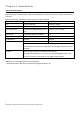
Chapter 1: Introduction Computer Requirements Personal computer attached to the WiFi Voice Gateway must meet the minimum system requirements as below. Note: The minimum requirements may vary by the cable company. IBM PC COMPATIBLE MACINTOSH** CPU Pentium preferred PowerPC or higher System RAM 512MB (1024MB preferred) 512MB (1024MB preferred) Operating System Windows* NT/2000/Me/XP/7/Vista, Mac OS** 7.6.
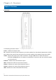
Chapter 2: Overview Chapter 2: Overview Front Panel The following illustration shows the front panel of the EMTA: Power ‐ Indicates the Power status. DS ‐ Indicates the status of Data reception by the cable modem from the Network (Downstream Traffic). US ‐ Indicates the status of Data transmission by the cable modem to the Network (Upstream Traffic). Online ‐ Displays the status of your cable connection.
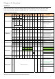
Chapter 2: Overview LED Behavior There will be 12 LEDs on TCG220. Looking at LED from TOP to Bottom: Power, DS, US, Online, LAN1, LAN2, LAN3, LAN4, WiFi, PHONE1, PHONE2, WPS. "ON" = the LED is light, "OFF" = the LED is gray, "FLASH" = the LED is blinking. BCM93383WVG Internet Power ON DS US Online ON ON ON On Boot‐up Operation ON LAN 2 3 4 ON ON ON ON X ON ON X X X X X X X X X Power on 0.25 sec 0.
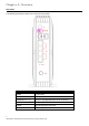
Chapter 2: Overview Rear Panel The following illustration shows the rear panel of the EMTA: Slot Description CABLE F‐Connector RESET Reset/Reboot this Cable modem ETHERNET 1 2 3 4 Ethernet 10/100/1000 BaseT RJ‐45 connector TEL 1 2 Telephony RJ‐11 connector 12VDC 12V DC‐IN Power connector DC Power switch Power ON/ OFF switch 5 Illustrations contained in this document are for representation only.
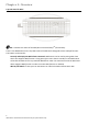
Chapter 2: Overview Top Side Panel for WPS WPS – Indicates the status of the WPS (Wi‐Fi Protected SetupTM) functionality. There is one WPS button on the Top Side Panel of TCG220 and is designed to have multiple function. This button can be used to: Securely and Simply Get WiFi Client Connected: WPS button can be used to paring WiFi client which also supports WPS function. A long press (press more than 2 seconds) on the WPS button will enable TCG220 scan for any available WPS device.
Chapter 2: Overview Important Information z z z The cable service to your home supports DOCSIS compliant two‐way modem access. Your internet account has been set up. A cable outlet near your PC and it is ready for cable modem service. Note: It is important to supply power to the modem at all times. Keeping your modem plugged in will keep it connected to the Internet. This means that it will always be ready when you are. Your cable company should always be consulted before installing a new cable outlet.
Chapter 3: Connections and setup Chapter 3: Connections and setup Connecting the EMTA to Computer This section explains the way to attach Cable TV wire to EMTA and to connect your EMTA to the Ethernet port on your personal computer and install the necessary software. Attaching the Cable TV Wire to EMTA You may find the Cable TV wire one of the following ways: z z Connected directly to a TV, a Cable TV converter box, or VCR.
Chapter 3: Connections and setup Connection to Computer and Telephone Make the connections to modem in the following sequence: z z Connect the plug from the AC power supply into the POWER AC ADAPTER jack on the EMTA, and plug the power supply into an AC outlet in the wall. Connect one end of the Ethernet cable to the Ethernet port on the back of your computer, and the other end to the ETHERNET port on the EMTA. Note: Use only the power supply that accompanied this unit.
Chapter 3: Connections and setup Activating the EMTA After you install the EMTA and turn it on for the first time (and each time the modem is reconnected to the power), it goes through several steps before it can be used. Each of these steps is represented by a different pattern of flashing lights on the front of the modem. Note: All indicators flash once prior to the initialization sequence. If all of the lights are flashing sequentially, it means the EMTA is automatically updating its system software.
Chapter 3: Connections and setup Accessing the Internet If enabled by your service provider; please proceed as follows: 1. 2. Once your host PC is properly configured. Start your web browser and type the CM IP address on the URL field. After connecting to the URL, you can see the login page. Please enter the username, password and then press Login button. The default username is "admin" and password is "password". Fig.
C Chapter r 3: Co onnectiions an nd setu up Staatus Web Page P Group Connectio on Th his page reports current connectio on status containing staartup proceedures, dow wnstream an nd upstream m staatus, CM on nline inform mation, and so on. The information i n can be useeful to yourr cable company’s support techn nician if you u’re having problems. Fig. 3: Connection Status 12 ustrations contained in this document aree for represen ntation only.
Chapter 3: Connections and setup Software The information section shows the hardware and software information about your gateway. The status section of this page shows how long your gateway has operated since last time being powered up, and some key information the Cable Modem received during the initialization process with your cable company. If Network Access shows “Allowed,” then your cable company has configured your gateway to have Internet connectivity.
Chapter 3: Connections and setup Security By default, the username is “admin” and the password is “password”. This is set by different actions (non exhaustive list): ‐ at the manufactory level, ‐ following a reset factory on the modem, ‐ following a reset from the operator, ‐ following a change by the user who wants to come back to the default setting after using its own settings When the current password is the default one, the user is strongly encouraged to change the default web password.
Chapter 3: Connections and setup Diagnostics This page offers basic diagnostic tools for you to use when connectivity problems occur. When you ping an Internet device, you send a packet to its TCP/IP stack, and it sends one back to yours. To use the ping Test, enter the information needed and press Start Test; the Result will be displayed in the lower part of the window. Press Abort Test to stop, and Clear Results to clear the result contents.
Chapter 3: Connections and setup Provisioning Mode This page allows set the eRouter IP provisioning mode. Default Provisioning mode is "RG". You can also configure this as "Bridge" mode. Configure TCG220 to Bridge mode will lost most of the Router function. Fig. 7: Provisioning mode settings. 16 Illustrations contained in this document are for representation only.
Chapter 3: Connections and setup Basic Web Page Group Setup This page allows configuration of the basic features of the broadband gateway related to your ISP's connection. LAN: Configure the LAN IP Address for TCG220. Interface/Prefix: IPv6 related information. WAN: TCG220 WAN interface information. Do NOT change the configuration setting which may cause severe performance impact, or Client PC may not be able to get internet connected. Fig.
Chapter 3: Connections and setup DHCP This page allows configuration and status of the optional internal DHCP server for the LAN. You can activate the DHCP server function for the LAN on this page, with this function activated, • your cable company’s DHCP server provides one IP address for your gateway, • and your gateway’s DHCP server provides IP addresses to your PCs. A DHCP server leases an IP address with an expiration time that can be configured.
Chapter 3: Connections and setup DDNS This page allows setup of Dynamic DNS service. z z z z z DDNS Service‐ Choose Enabled ( www.DynDNS.org ) to enable the basic setting. Choose Disabled to close the basic setting. Username‐ The username that you registered with your DDNS provider. Password‐ The password that you registered with your DDNS provider Host Name‐ The domain name or host name that is registered with your DDNS provider Status‐ It shows the DDNS service status whether it is enabled or disabled.
Chapter 3: Connections and setup Backup This page allows you to save your current settings locally on your PC, or restore settings previously saved. Customer may backup their settings on TCG220. And restore the configuration if necessary. Fig. 11: Backup Settings 20 Illustrations contained in this document are for representation only.
C Chapter r 3: Co onnectiions an nd setu up Ad dvance Web b Page Grou up Option Th his page allo ows configuration of ad dvanced feaatures of the e broadban nd gateway. Fig. 12: Options Confiiguration WA AN Blocking prevents others on the WAN sid de from being able to ping p your gaateway. Witth WAN Blo ocking enab bled, your gateway g will not respon nd to pings it receives, effectively "hiding" yo our gatewayy. 21 ustrations contained in this document aree for represen ntation only.
Chapter 3: Connections and setup IPsec PassThrough enables IPsec type packets to pass between WAN and LAN. IPsec (IP Security) is a security mechanism used in Virtual Private Networks (VPNs). PPTP PassThrough enables PPTP type packets to pass between WAN and LAN. PPTP (Point to Point Tunneling Protocol) is another mechanism sometimes used in VPNs. Remote Config Management makes the configuration web pages in your gateway accessible from the WAN side.
Chapter 3: Connections and setup IP Filtering This page enables you to enter the IP address ranges of PCs on your LAN that you don’t want to have outbound access to the WAN. These PCs can still communicate with each other on your LAN, but packets they send to WAN addresses are blocked by the gateway. Fig. 13: IP Filtering Settings 23 Illustrations contained in this document are for representation only.
Chapter 3: Connections and setup MAC Filtering This page allows configuration of MAC address filters in order to block internet traffic to specific network devices on the LAN. This feature only applies to IPv4 traffic. Fig. 14: MAC Filtering Settings 24 Illustrations contained in this document are for representation only.
Chapter 3: Connections and setup Port Filtering This page allows you to enter ranges of destination ports (applications) that you don’t want your LAN PCs to send packets to. Any packets your LAN PCs send to these destination ports will be blocked. For example, you could block access to worldwide web browsing (http = port 80) but still allow email service (SMTP port 25 and POP‐3 port 110). To enable port filtering, set Start Port and End Port for each range, and click Apply.
Chapter 3: Connections and setup Forwarding For LAN Ù WAN communications, the gateway normally only allows you to originate an IP connection with a PC on the WAN; it will ignore attempts of the WAN PC to originate a connection onto your PC. This protects you from malicious attacks from outsiders. However, sometimes you may wish for anyone outside to be able to originate a connection to a particular PC on your LAN if the destination port (application) matches one you specify. Fig.
Chapter 3: Connections and setup Port Triggers Some Internet activities, such as interactive gaming, require that a PC on the WAN side of your gateway be able to originate connections during the game with your game playing PC on the LAN side. You could use the Advanced‐Forwarding web page to construct a forwarding rule during the game, and then remove it afterwards (to restore full protection to your LAN PC) to facilitate this.
Chapter 3: Connections and setup DMZ Host Use this page to designate one PC on your LAN that should be left accessible to all PCs from the WAN side, for all ports. e.g., if you put an HTTP server on this machine, anyone will be able to access that HTTP server by using your gateway IP address as the destination. A setting of “0” indicates NO DMZ PC. “Host” is another Internet term for a PC connected to the Internet. Fig.
Chapter 3: Connections and setup RIP (Routing Information Protocol Setup) This feature enables the gateway to be used in small business situations where more than one LAN (local area network) is installed. The RIP protocol provides the gateway a means to “advertise” available IP routes to these LANs to your cable operator, so packets can be routed properly in this situation. Your cable operator will advise you during installation if any setting changes are required here. Fig.
Chapter 3: Connections and setup Firewall Web Page Group Basic This page allows configuration of Firewall features. It is highly recommended that the Firewall is left enabled at all times for protection against Denial of Service attacks. Fig. 20: Firewall Basic configuration 30 Illustrations contained in this document are for representation only.
Chapter 3: Connections and setup Filtering This page allows the filtering of outbound connections, restricting or granting access to specific MAC Addresses. Filters with no MAC Address entered will apply to ALL MAC Addresses. The URL field is intended to be used to block or allow access to specific sites ( cnn.com, google.com, etc. ). Filters with no ports entered will apply to ALL ports. Fig. 21: Filtering configuration 31 Illustrations contained in this document are for representation only.
Chapter 3: Connections and setup Local Log The gateway builds a log of firewall blocking actions that the firewall has taken. Using the Local Log page lets you specify an email address to which you want the gateway to email this log. You must also tell the gateway your outgoing (i.e. SMTP) email server’s name, so it can direct the email to it. Enable Email Alerts has the gateway forward email notices when Firewall protection events occur. Click E‐mail Log to immediately send the email log.
Chapter 3: Connections and setup Remote Log The Remote Log page allows you to specify the IP address where a SysLog server is located on the LAN Side and select different types of firewall events that may occur. Then, each time such an event occurs, notification is automatically sent to this log server. Fig. 23: Remote Log Configuration 33 Illustrations contained in this document are for representation only.
Chapter 3: Connections and setup Wireless Web Page Group Radio To set the basic configuration for the wireless features, click RADIO from the Wireless menu. These must match the settings you make on your wireless‐equipped PC on the LAN side. Fig. 24: Radio configuration Wireless Interface: Choose the wireless interface on the EMTA. Wireless: Enable or disable the wireless function. Country: Display the country code you currently use. Output Power: Choose output power of the device. 802.11 Band: Choose 2.
Chapter 3: Connections and setup Bandwidth: For wireless signal of this AP Sideband for Control Channel (40 MHz only): If Bandwidth is 40 MHz this function will be enabled. Control channel: Choose the wireless channel to use. Regulatory Mode: 802.11d and 802.11h for choose. OBSS (Overlap Basic Service Set) Coexistence: Overlapping Basic service set coexistence, enable or disable this function.
Chapter 3: Connections and setup Primary Network This page allows configuration of the Primary Wireless Network and its security settings. Supports WPA/WPA2, WPA‐PSK/WPA2‐PSK, WEP 64‐bits, WEP 128‐bits and WPS Securities. Fig. 25: primary Network configuration 36 Illustrations contained in this document are for representation only.
Chapter 3: Connections and setup WPA (Wi‐Fi Protected Access)/WPA2: It must be used in connection with an authentication server such as RADIUS to provide centralized access control and management. It can provide stronger encryption and authentication solution than none WPA modes. WPA2 is the second generation of WPA security. There are two types for choose AES and TKIP+AES.
Chapter 3: Connections and setup Keys will not be shown on this page. If selected, the data is encrypted using the key before being transmitted. Shared Key Authentication: Decide whether to set the shared key Optional or Required by selecting from the drop‐down menu. Network Key 1 to 4: This allows you to enter four sets of the WEP key. For 64‐bit WEP mode, the key length is 5 characters or 10 hexadecimal digits.
Chapter 3: Connections and setup Automatic Security Configuration: Right side on the page, Auto Security Configuration can be enabled with WPS (Wi‐Fi Protect SetupTM). WPS (Wi‐Fi Protect SetupTM): Its easy and secure way of configuring and connecting, make the CM is the AP and the connect PC is STA.
Chapter 3: Connections and setup 802.11 Advanced This page allows configuration of data rates and Wi‐Fi thresholds. CAUTION: It is not recommended that these settings be modified without direct knowledge or instructions to do so. Modifying these settings inappropriately could seriously degrade network performance. Fig. 26: 802.11 Advanced Settings 54gTM Mode: Under 802.11n‐mode OFF this option to choose 54g mode or force 802.11b only.
Chapter 3: Connections and setup Multicast Set: For users, in order to connect to the AP, set the baseline level to deliver. Lower multicast rates mean weaker, farther signals are allowed to connection. Higher multicast rates mean that only close, strong signals are allowed. NPHY Rate: Set Physical Layer rate, only applicable when the 802.11n‐mode set as auto. Legacy Rate: When AP released to share the band with existing legacy device, 802.11g/b/a devices.
Chapter 3: Connections and setup 802.11 Access Control This page allows configuration of the Access Control to the AP as well as status on the connected clients. Fig. 27: 802.11 Access Control configurations MAC Restrict Mode: Restrict specific client cannot allow access the AP by MAC address.
Chapter 3: Connections and setup WMM This page allows configuration of the Wi‐Fi Multimedia QoS. Fig. 28: 802.11 WMM configurations WMM Support: This field allows you to enable WMM to improve multimedia transmission. No‐Acknowledgement: This field allows you to enable WMM No‐Acknowledgement. Enable this avoids retransmission on highly time‐critical data. Power Save Support: This field allows you to enable WMM Power‐Save‐Support.
Chapter 3: Connections and setup and voice (AC_VO). Transmit parameters include contention window (CWmin CWmax) , arbitration Inter Frame Spacing Number AIFSN, and Transmit opportunity Limit (TXOP limit). WMM TXOP parameters: Specifies the TXOP parameter for the 4 Access Priority Categories :Best effort (AC_BE), Background (AC_BK), Video (AC_VI) and voice(AC_VO). WMM Transmit parameters include Short Retry Limit , Short Fallbk Limit , Long Retry Limit , Long Fallbk Limit.
Chapter 3: Connections and setup WDS This page allows configuration of WDS (Wireless Distribution System) features. Fig. 29: WDS configuration TCG220 can allow to communicate with other "extender" wireless access points either exclusively or mixed with communications to local PCs. Use this page to designate the remote devices, the gateway is allowed to communicate with, and to select the WDS mode.
Chapter 3: Connections and setup Media This page allows configuration of Wireless Media features. Fig. 30: 802.11 Media Advanced Feature Configuration Band Steering is a new feature that TCG220 has and will balancing the WiFi loading and performance on both 2.4G and 5G band. When enabled, TCG220 will send 5G enabled client which connected on 2.4G to the 5G interface (since TCG220 is a Dual Band Dual Concurrent Cable Voice WiFi Gateway), vice versa. This will also requires the support from WiFi Client.
Chapter 3: Connections and setup MTA Web Page Group Status This page displays initialization status of the MTA. Fig.31: MTA Status Event Log This page displays the MTA Event Log. Fig. 32: MTA Event Log 47 Illustrations contained in this document are for representation only.
Chapter 3: Connections and setup Logout Web Page Group This page warning you are logged out, click "Back to Login" return to Login page. Fig. 33: Logout Page 48 Illustrations contained in this document are for representation only.
Chapter 4: Additional Information Chapter 4: Additional Information General Troubleshooting You can correct most problems you have with your product by consulting the troubleshooting list that follows. I cannot access the Internet. Check all of the connections to your EMTA. Your Ethernet card may not be working well. Check the documentation for more information. The Network Properties of your operating system may not be setting correctly. Check with your ISP or cable company.
Chapter 4: Additional Information If the EMTA is connected to existing house telephone wiring, make sure that another telephone service is not connected. The other service can normally be disconnected at the Network Interface Device located on the outside of the house. If using the second line on a two‐line telephone, use a 2‐line to 1‐line adapter cable. 50 Illustrations contained in this document are for representation only.
Chapter 4: Additional Information Service Information If you purchased or leased your EMTA directly from your cable company, then warranty service for the EMTA may be provided through your cable provider or its authorized representative. For information on the following, please contact your cable company. See the enclosed warranty card if you purchased your EMTA from a retailer.
Chapter 4: Additional Information Glossary 10BaseT – Unshielded, twisted pair cable with an RJ‐45 connector, used with Ethernet LAN (Local Area Network). "10" indicates speed (10 Mbps), "Base" refers to baseband technology, and "T" means twisted pair cable. Authentication ‐ The process of verifying the identity of an entity on a network. DHCP (Dynamic Host Control Protocol) – A protocol with which allows a server to assign IP addresses dynamically to hosts on the fly.
Chapter 4: Additional Information TCP/IP (Transmission Control Protocol/Internet Protocol) – A networking protocol that provides communication across interconnected networks, between computers with diverse hardware architectures and various operating systems. TFTP ‐ Trivial File Transfer Protocol, the system by which the Media Terminal Adapter’s configuration data file is downloaded.
Chapter 4: Additional Information CAUTION for UL(Check caution label on gift box) North American Cable Installer: This reminder is provided to call your attention to Article 820.93 of the National Electrical Code (Section 54 of the Canadian Electrical Code, Part 1) which provides guidelines for proper grounding and, in particular, specifies that the cable ground shall be connected to the grounding system of the building as close to the point of cable entry as practical.
Chapter 4: Additional Information Federal Communication Commission Interference Statement This device complies with Part 15 of the FCC Rules. Operation is subject to the following two conditions: (1) This device may not cause harmful interference, and (2) this device must accept any interference received, including interference that may cause undesired operation. This equipment has been tested and found to comply with the limits for a Class B digital device, pursuant to Part 15 of the FCC Rules.
Chapter 4: Additional Information Radiation Exposure Statement: This equipment complies with FCC radiation exposure limits set forth for an uncontrolled environment. This equipment should be installed and operated with minimum distance 27cm between the radiator & your body. Note: The country code selection is for non‐US model only and is not available to all US model. Per FCC regulation, all WiFi product marketed in US must fixed to US operation channels only.
Federal Communication Commission Interference Statement This device complies with Part 15 of the FCC Rules. Operation is subject to the following two conditions: (1) This device may not cause harmful interference, and (2) this device must accept any interference received, including interference that may cause undesired operation. This equipment has been tested and found to comply with the limits for a Class B digital device, pursuant to Part 15 of the FCC Rules.
Radiation Exposure Statement: This equipment complies with FCC radiation exposure limits set forth for an uncontrolled environment. This equipment should be installed and operated with minimum distance 20cm between the radiator & your body. Note: The country code selection is for non-US model only and is not available to all US model. Per FCC regulation, all WiFi product marketed in US must fixed to US operation channels only.